

Portable gate hoist and operating method thereof
An opening and closing device, portable technology, applied in water conservancy projects, marine engineering, coastline protection, etc., can solve the problem that the gate cannot be raised and lowered quickly
- Summary
- Abstract
- Description
- Claims
- Application Information
AI Technical Summary
Problems solved by technology
Method used
Image

Examples
Embodiment Construction
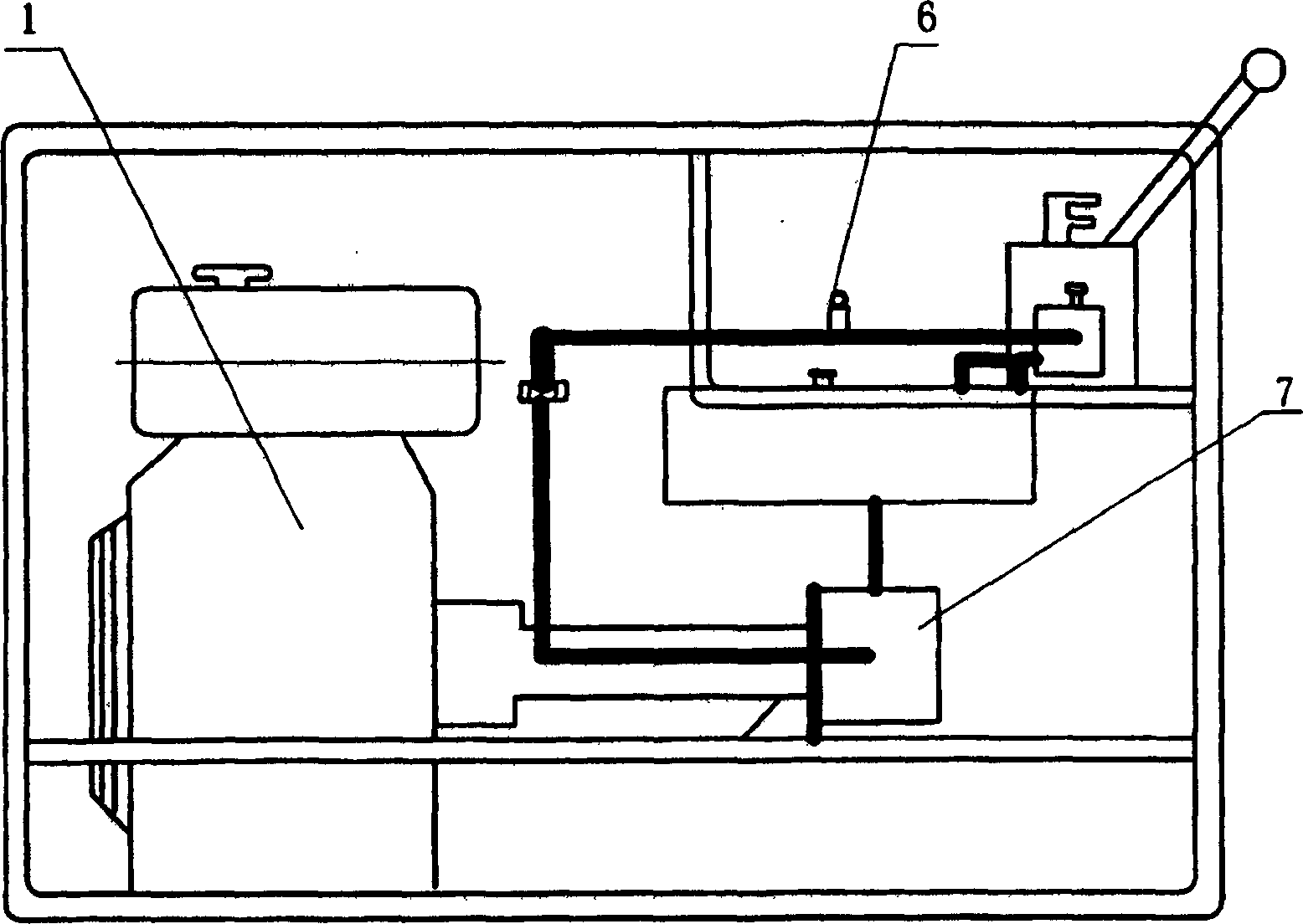
[0017] Table 1 shows the main technical parameters of a portable gate opening and closing device
[0018] Dimensions (length × width × height mm)
700×450×450
Weight(KG)
40
Maximum torque (N·m)
119
Speed(r / min)
120~128
Hydraulic oil
YA-N6 GB2512-81
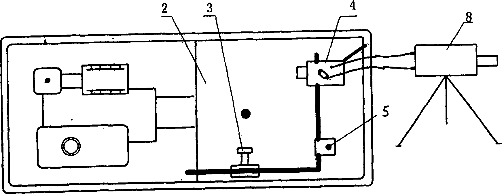
[0019] The working environment of the hydraulic gate hoist is to lift and lower the gate when the fixed winch hoist and the fixed screw hoist with a manual device have no power supply.
[0020] Specific operation method
[0021] 1. Completely disconnect the power supply of the fixed hoist before installation.
[0022] 2. Use two hydraulic oil transmission pipes to connect the cycloid motor with the equipment port; ensure that the ferrule is connected in place.
[0023] 3. Check the joystick of the transposition valve, and ensure that the joystick of the transposition valve is in the middle position.
[0024] 4. Start the engine, and warm up the engine and g...
PUM
 Abstract
Description
Claims
Application Information