
Adjustable diffuser vane structure for centrifugal compressor

A centrifugal compressor and blade structure technology, applied in machines/engines, mechanical equipment, liquid fuel engines, etc., can solve the problems of reduced compressor efficiency and gas leakage, reducing resistance, reducing gap leakage, and improving work efficiency. Effect

Active Publication Date: 2018-10-19
BEIJING INSTITUTE OF TECHNOLOGYGY
View PDF6 Cites 0 Cited by
  • Summary
  • Abstract
  • Description
  • Claims
  • Application Information

AI Technical Summary

Problems solved by technology

Due to the pressure difference between the pressure surface and the suction surface of the diffuser vane, and the gap between the two end surfaces and their respective opposite walls, the gas leaks from the side with higher pressure to the side with lower pressure, which will cause a significant decrease in the efficiency of the compressor.

Method used


Image

  • Adjustable diffuser vane structure for centrifugal compressor
  • Adjustable diffuser vane structure for centrifugal compressor
  • Adjustable diffuser vane structure for centrifugal compressor

Examples


Embodiment Construction

[0037] The following will clearly and completely describe the technical solutions in the embodiments of the present invention with reference to the accompanying drawings in the embodiments of the present invention. Obviously, the described embodiments are only some, not all, embodiments of the present invention. Based on the embodiments of the present invention, all other embodiments obtained by persons of ordinary skill in the art without making creative efforts belong to the protection scope of the present invention.

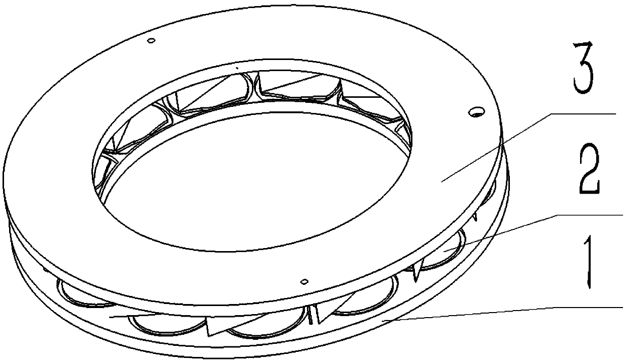
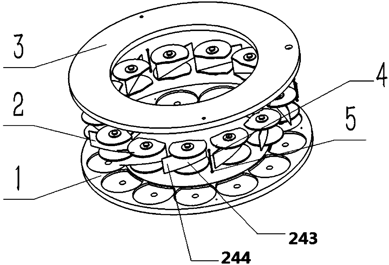
[0038] Such as figure 1 and figure 2 As shown, the embodiment of the present invention discloses an adjustable diffuser vane structure for a centrifugal compressor, including support disc one 1, a plurality of adjustable diffuser vane assemblies 2 and support disc two 3, support disc one 1 and support Disk 2 and 3 are set concentrically and are all ring-shaped. The adjustable diffuser blade assembly 2 is annular and evenly spaced and installed between the su...


PUM


Abstract

The present invention discloses an adjustable diffuser vane structure for a centrifugal compressor, which includes: a first support tray, a plurality of adjustable diffuser vane components and a second support tray. The first support tray and the second support tray are concentrically fixed and connected, both of which have a ring structure. The adjustable diffuser vane components are uniformly and annularly distributed with equal spacing, and are installed between the first support tray and the second support tray. Diffuser flow passages are formed among the adjustable diffuser vane components and a diffuser is formed by a series of diffuser flow passages. The flow area of the diffuser is adjusted through rotation of the adjustable diffuser vane components. At least one of the two end surfaces of the adjustable diffuser vane components is placed in a groove of the first support tray or a groove of the second support tray, so as to reduce the amount of gas leak caused by voids betweenthe two ends of a conventional adjustable diffuser vane and accordingly improve the operating efficiency of the centrifugal compressor.

Description

technical field [0001] The invention relates to the technical field of centrifugal compressors, in particular to an adjustable diffuser vane structure for reducing gap leakage flow. Background technique [0002] Due to its adjustable flow section, the variable geometry centrifugal compressor can form a good match with the vehicle engine in the full range of working conditions, thus improving the acceleration, power and other performance of the engine more effectively than other centrifugal compressors, so It is increasingly used in vehicle engines. In order to ensure the free rotation of the diffuser blades, it is necessary to design a certain gap between the two ends of the diffuser blades and their respective opposite walls. Because the pressure of the pressure surface of the diffuser blade is different from that of the suction surface, and the gap between the two end surfaces and their respective opposite walls causes the gas to leak from the side with higher pressure to...

Claims


Application Information

Patent Timeline
IPC IPC(8): F04D29/46
Inventor 祁明旭王鹏霄马朝臣石志伟
Owner BEIJING INSTITUTE OF TECHNOLOGYGY
Features
  • Generate Ideas
  • Intellectual Property
  • Life Sciences
  • Materials
  • Tech Scout
  • Unparalleled Data Quality
  • Higher Quality Content
  • 60% Fewer Hallucinations
Learn More