Variable gauge bogie wheel pair orbital transfer performance and reliability test stand

A reliability and bogie technology, which is applied in the field of wheelset track change performance and reliability test benches of variable gauge bogies, can solve the problems of difficult wheelset track change performance and reliability test, etc., so as to increase reliability and safety. sexual effect

Pending Publication Date: 2018-10-19
JILIN UNIV
0 Cites 10 Cited by

AI-Extracted Technical Summary

Problems solved by technology

[0004] In order to solve the problem that it is difficult to carry out the track change performance and reliability test of the wheel set in the actual operation of the variable gauge train in the prior art, the present invention provides a test platform for the track change performance and reliabil...

Method used

Described left guide rail 16 and right guide rail 17 are respectively welded on the two ends of cylinder 18 outer circles, and the distance L0 of the inner surface of described left guide rail 16 and right guide rail 17 is variable gauge steering all the time The manufacturing error of the thickness of the frame wheel + 1 ~ 2mm; the left guide rail 16 is provided with a left guide rail start end face 16-1 and a left guide rail end face 16-2, and the right guide rail 17 is provided with a right Guide rail start end face 17-1 and right guide rail end face 17-2; described left guide rail start end face 16-1 and left guide rail end face 16-2 or right guide rail start end face 17-1 and The distance between the end face 17-2 of the right guide rail along the direction L1 of the roller axis is the distance that a single wheel needs to change the gauge when the gauge of the variable-gauge bogie is converted. The included angle of the terminating end face 17-2 or the included angle between the terminating end face 16-2 of the left guide rail and the starting end face 17-1 of the right guide rail is equal, and the selection basis of the size of the included ang...

Abstract

The invention discloses a variable gauge bogie wheel pair orbital transfer performance and reliability test stand. The test stand mainly comprises a motor, a motor support, a first coupling, a double-output shaft reducer, a concave base, a second coupling, a first bearing, a first bearing support, a second bearing, a second bearing support, a first gauge adjustment roller assembly, a second gaugeadjustment roller assembly, a variable gauge wheel pair, a gantry wheel pair fixing device and a pedestal, wherein the first gauge adjustment roller assembly or the second gauge adjustment roller assembly comprises a left guide rail, a right guide rail, a roller, a roller shaft, an adjustment pad and a locking nut, and the gantry wheel pair fixing device comprises a column, a supporting platform and a wheel pair fixing supporting block. The test stand is advantaged in that the structure is simple, the orbital transfer action of the variable gauge wheel pair can be simulated in a cycle mode, and a problem of difficulty in testing variable gauge performance and reliability of the wheel pair existing in a variable gauge train in the actual running process in the prior art is solved.

Application Domain

Technology Topic

Transfer - actionEngineering +4

Image

  • Variable gauge bogie wheel pair orbital transfer performance and reliability test stand
  • Variable gauge bogie wheel pair orbital transfer performance and reliability test stand
  • Variable gauge bogie wheel pair orbital transfer performance and reliability test stand

Examples

  • Experimental program(1)

Example Embodiment

[0025] The present invention will be described in detail below in conjunction with the drawings:
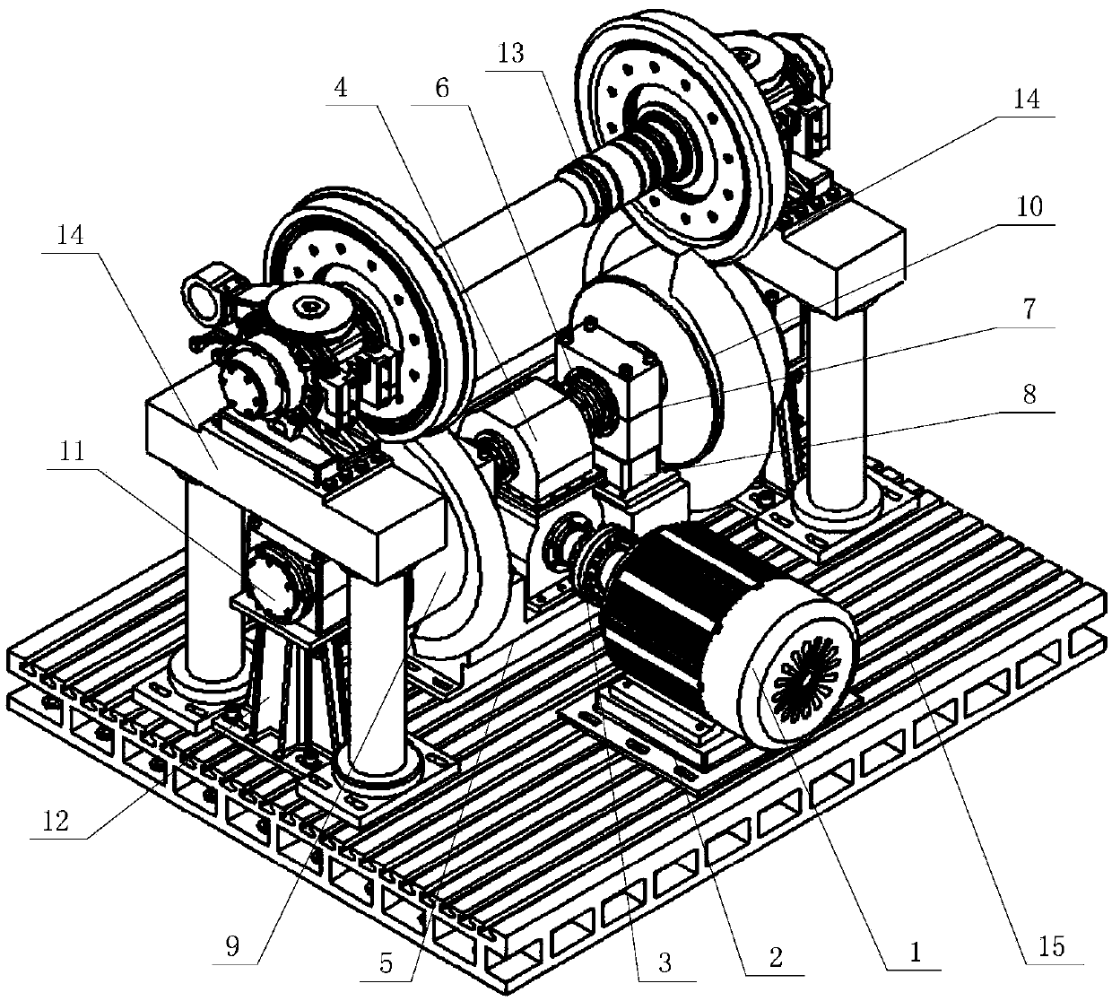
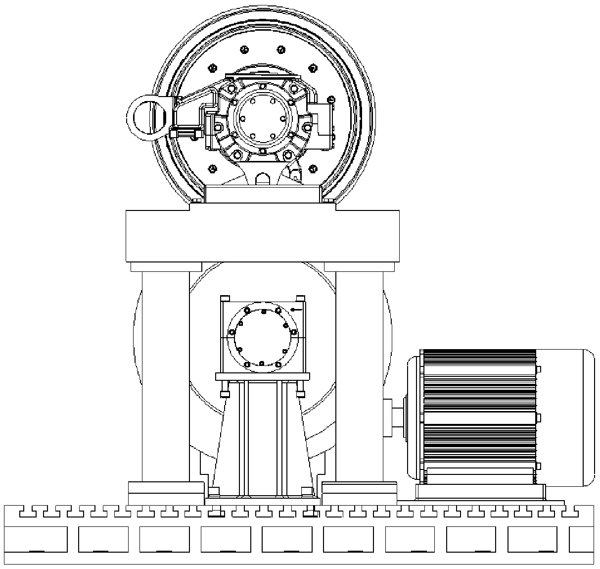
[0026] Refer to Figure 1 to Figure 4 , The track change performance and reliability test bed of the track-changing bogie wheel set mainly includes the motor 1, the motor support 2, the No. 1 coupling 3, the dual output shaft reducer 4, and the concave base 5 , No. 2 shaft coupling 6, No. 1 bearing 7, No. 1 bearing support 8, No. 1 gauge adjustment roller assembly 9, No. 2 gauge adjustment roller assembly 10, No. 2 bearing 11, No. 2 bearing support 12, The variable gauge wheel set 13, the gantry wheel set fixing device 14 and the base 15; the output shaft of the motor 1 is connected to the input shaft of the double output shaft reducer 4 through the first coupling 3. 1 is fixed on the motor support 2 by bolts, and the motor support 2 is fixedly installed on the base 15; the two output shafts of the dual output shaft reducer 4 are respectively passed through the second coupling 6 and the first rail Pitch adjustment roller assembly 9 and No. 2 gauge adjustment roller assembly 10 are connected; the axial center lines of the two output shafts of the dual output shaft reducer 4, and the roller shaft 19 of the No. 1 gauge adjustment roller assembly 9 To the center line, the axial center line of the roller shaft 19 of the No. 2 gauge adjustment roller assembly 10 and the axle axial center line of the variable gauge wheel set 13 are arranged in the same horizontal plane; the dual output shaft reducer 4 The No. 1 bearing support 8 is installed on the concave base 5 by bolts, and the concave base 5 is fixedly installed on the base 15 by bolts.
[0027] Refer to Figure 5 to Figure 8 , The No. 1 gauge adjustment roller assembly 9 or No. 2 gauge adjustment roller assembly 10 includes a left guide rail 16, a right guide rail 17, a roller 18, a roller shaft 19, an adjustment washer 20 and a lock nut 21; The No. 1 gauge adjustment roller assembly 9 and the No. 2 gauge adjustment roller assembly 10 have the same structure, but the structure forms are mirror images of each other; the two gauge adjustment roller assemblies 9 and the No. 2 gauge adjustment roller assembly 10 The sides are respectively supported by the No. 1 bearing 7 and the No. 2 bearing 11; the No. 1 gauge adjustment roller assembly 9 and the No. 2 gauge adjustment roller assembly 10 are arranged symmetrically along the longitudinal centerline. When the motor 1 rotates, the No. 1 track The gauge adjustment roller assembly 9 and the No. 2 gauge adjustment roller assembly 10 rotate at the same time; the main function of the No. 1 gauge adjustment roller assembly 9 or the No. 2 gauge adjustment roller assembly 10 is to interact with the gauge-changing wheel through The rotation of the rollers pushes the wheels on both sides to move inward or outward at the same time relative to the axle of the gauge-changing bogie to realize the gauge-change of the wheel set. Each time the rollers turn, the wheel completes from gauge a to gauge b, and then Periodic action from gauge b to gauge a, and with the continuous rotation of the roller, the cycle of the wheel continues to reciprocate.
[0028] The left guide rail 16 and the right guide rail 17 are respectively welded to the two ends of the outer circle of the drum 18, and the distance between the left guide rail 16 and the inner side surface of the right guide rail 17 is L 0 It is always the manufacturing error of the thickness of the variable-gauge bogie wheel of +1-2mm; the left guide rail 16 is provided with a left guide rail starting end surface 16-1 and a left guide rail ending end surface 16-2. The guide rail 17 is provided with a right guide rail start end surface 17-1 and a right guide rail end surface 17-2; the left guide rail start end surface 16-1 and the left guide rail end end surface 16-2 or the right guide rail start The starting end surface 17-1 and the right guide rail end surface 17-2 are along the roller axis direction L 1 The distance is the distance that a single wheel needs to change the gauge when changing the gauge of the variable gauge bogie, the angle between the starting end surface 16-1 of the left guide rail and the ending end surface 17-2 of the right guide rail or the end of the left guide rail The included angle between the end surface 16-2 and the starting end surface 17-1 of the right guide rail is equal. The selection basis of the included angle is to ensure that when the wheel transitions from the ending end surface 16-2 of the left guide rail to the starting end surface 17-1 of the right guide rail Or when transitioning from the end surface 17-2 of the right guide rail to the starting end surface 16-1 of the left guide rail, the wheel does not interfere with the movement of the left guide rail 16 and the right guide rail 17; the adjusting shim 20 is arranged in On both sides of the roller 18, the adjustment spacers 20 are used to facilitate the adjustment of the No. 1 gauge adjustment roller assembly 9 or the No. 2 gauge adjustment roller assembly 10 according to the initial gauge of the variable gauge wheel set 13 to ensure the inner and outer guide rails Reliable contact with the wheel set and precise track change; the inner hole of the roller 18 is provided with a spline groove, and is installed with the roller shaft 19 through splines, and can rotate with the roller shaft 19; the roller 18 is connected to both sides The adjusting washer 20 realizes its axial positioning on the roller shaft 19 through the lock nut 21;
[0029] Refer to Picture 11 with Picture 12 The gantry type wheel set fixing device 14 includes a wheel set fixing support block 22, a support platform 23 and a column 24. Two gantry type wheel set fixing devices 14 with the same structure are arranged symmetrically along the longitudinal centerline. The roller assembly 9 and the outer side of the No. 2 gauge adjustment roller assembly 10 are mainly used to support and fix the variable gauge wheel set 13, so that the wheel set is suspended and unloaded and the two wheels and the No. 1 gauge adjustment roller assembly 9 and The position of the No. 2 gauge adjusting roller assembly 10 is exactly matched; the wheel set fixing support block 22 is provided with a bearing shoe support surface 22-1 and a lower axle box positioning groove 22-2, so as to realize the vertical movement of the bogie axle box. For positioning in the vertical, horizontal and vertical directions, the wheel set fixing support block 22 is fixed and installed on the support platform 23 by bolts. The lower part of the support platform 23 is supported by two round pipe columns 24. The upper ends of the columns 24 are connected to the support platform 23 by bolts. , The lower end is fixedly installed on the base 15 by bolts; the variable-gauge wheel set 13 is supported by two gantry-type wheel-set fixing devices 14. The two bearing shoes of the variable-gauge wheel set 13 are The supporting surface 22-1 is in contact, and the lower part of the lower axle box shell of the variable gauge wheel set 13 is just placed in the lower axle box positioning groove 22-2, so that the position of the variable gauge wheel set 13 is fixed and the two wheels are unloaded.

PUM

no PUM

Description & Claims & Application Information

We can also present the details of the Description, Claims and Application information to help users get a comprehensive understanding of the technical details of the patent, such as background art, summary of invention, brief description of drawings, description of embodiments, and other original content. On the other hand, users can also determine the specific scope of protection of the technology through the list of claims; as well as understand the changes in the life cycle of the technology with the presentation of the patent timeline. Login to view more.

Similar technology patents

Hacking defending implementation method and device

Owner:MICRO DREAM TECHTRONIC NETWORK TECH CHINACO

Cheating prevention electronic weighing apparatus calibrating system and method

Owner:CHENGDU JIUZHOU ELECTRONIC INFORMATION SYSTEM CO LTD

Classification and recommendation of technical efficacy words

Why Eureka
Try Eureka