
Method for placing scribing groove pattern

A technology for dicing grooves and graphics, which is applied in special data processing applications, instruments, electrical digital data processing, etc., and can solve problems such as manual placement, errors, and measurement errors

Inactive Publication Date: 2018-10-19
SHANGHAI HUAHONG GRACE SEMICON MFG CORP
View PDF7 Cites 5 Cited by
  • Summary
  • Abstract
  • Description
  • Claims
  • Application Information

AI Technical Summary

Problems solved by technology

However, when the size of the chip involved is large, there are many marks and PCMs, the algorithm of the existing tools cannot be placed, and only manual placement is used, which leads to manual operation when designing frame data, forgetting to align the mark alignment requirements, resulting in error occurred
The alignment marks in the exposure interval cannot be aligned normally, which will cause errors in the measurement and bring troubles to the project

Method used


Image

  • Method for placing scribing groove pattern
  • Method for placing scribing groove pattern
  • Method for placing scribing groove pattern

Examples


Embodiment Construction

[0019] The invention implements a method for placing and aligning graphics, which can place as many graphics as possible under the premise of ensuring the alignment of graphics. This method solves the problem that there are too many alignment graphics and cannot be placed in the past.

[0020] The principle of the present invention is to place and align graphics through mapping, Figure 11 The steps of the invention are shown:

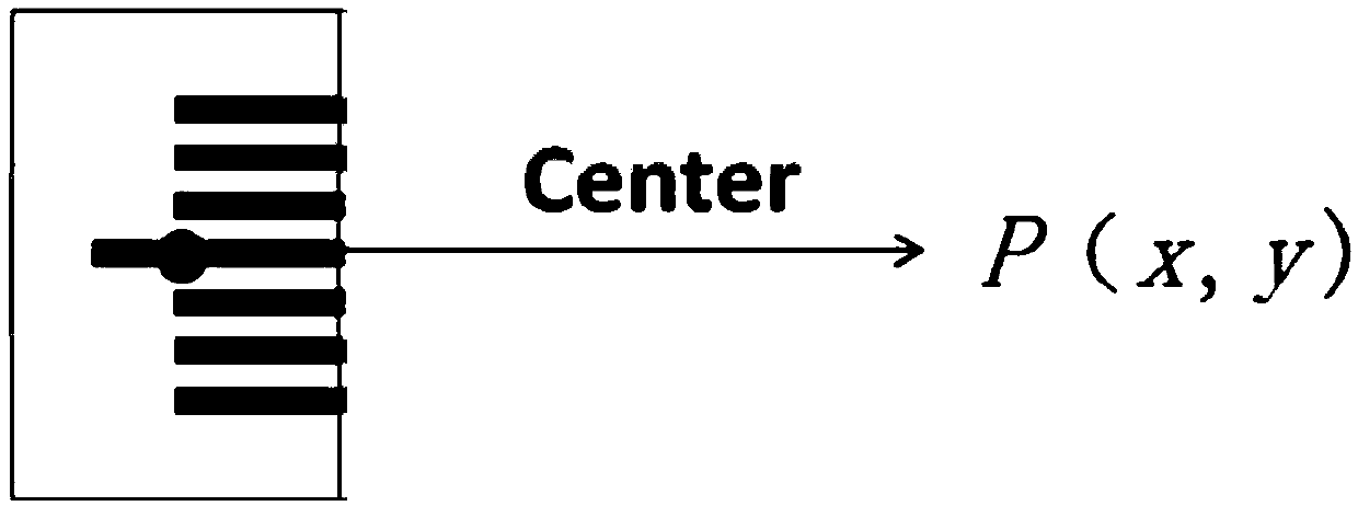
[0021] Step 1. Calculate the coordinates (x, y) of the center point of the graphic as a reference point placed in the coordinate system of the scribing groove.

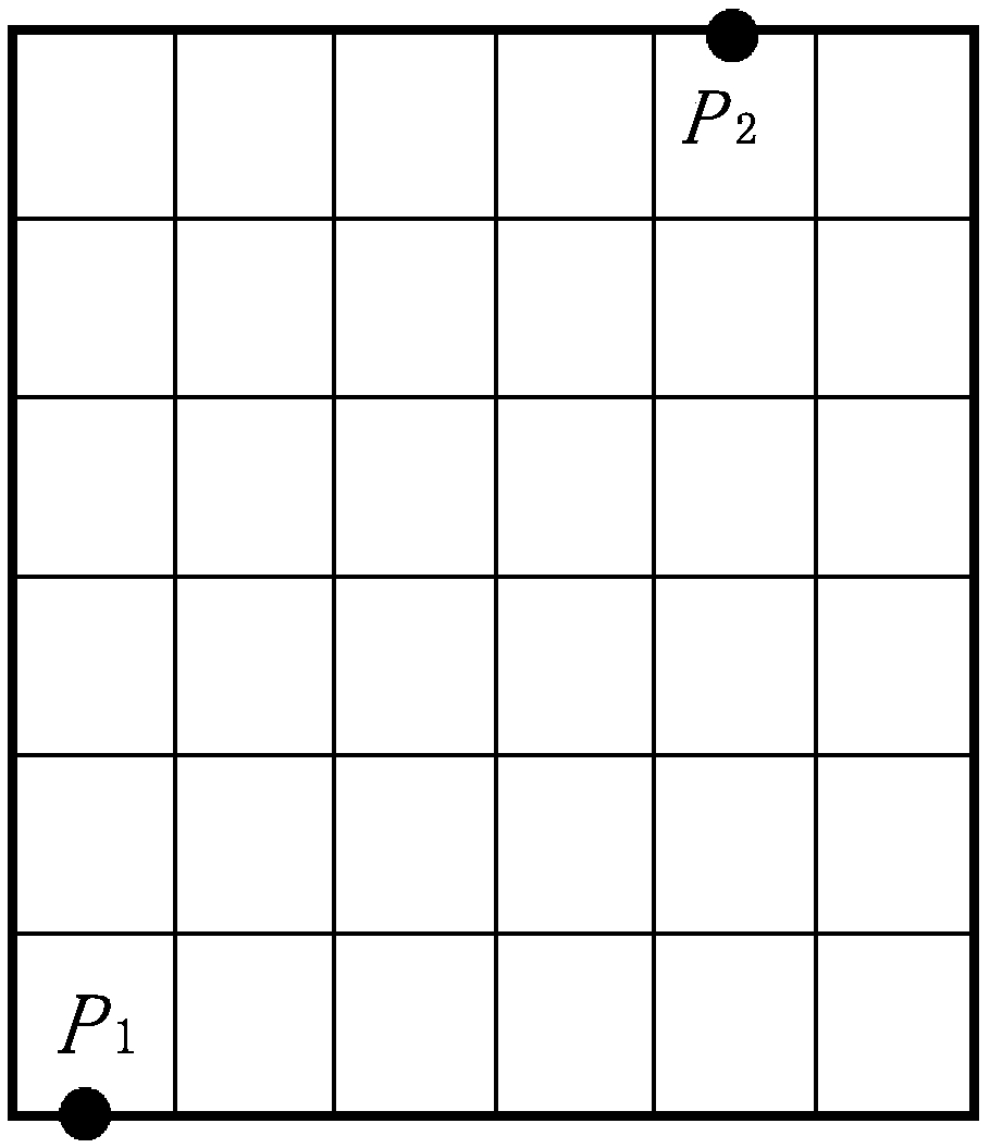
[0022] Step 2. Divide the dicing groove into four blocks: L, R, T, and B areas, representing left, right, upper, and lower areas respectively. Such as Figure 4 shown.

[0023] Step 3, first calculate the placement position of the L area. Such as Figure 5 As shown, the calculated position is the point closest to the origin of the scribe groove in the L area. The formula is as follows: ...


PUM


Abstract

The invention discloses a method for placing a scribing groove pattern, comprising the following steps: step 1, calculating the coordinates (x, y) of a central point of a pattern; step 2, dividing a slicing groove into four region blocks: L, R, T and B regions; step 3, calculating the placement position of the L region; step 4, mapping the obtained calculated positions to each of R, T and B regions through coordinate transformation; and step 5, if an effective coordinate of each of R, T and B regions cannot be generated, correcting the position of the L region, and repeating the step 4. The invention utilizes the coordinate projection transformation and the inverse marking correction, and after testing, the scribing groove pattern can be successfully placed under the condition of more scribing groove patterns, and the symmetry is maintained.

Description

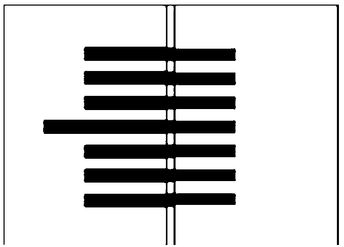
technical field [0001] The invention relates to the field of integrated circuit manufacturing, in particular to a method for placing scribe groove patterns. Background technique [0002] During the mask design process, some scribe groove patterns need to be placed, and these patterns are mainly used for alignment or other purposes. Such as figure 1 The alignment mark (ROTATION) pattern shown is used to test the rotation error between masks. The alignment marks between the two exposure areas (shot) are spliced ​​together to form a complete figure. Since these graphics need to be spliced, the alignment needs to be maintained between the graphics. The previous technology mainly uses software to calculate the center point of the graphics as a reference point placed in the scribe groove coordinate system. Such as figure 2 As shown, point P is a reference point in the scribe groove coordinate system, and its coordinate is P(x, y). When placed in the scribe slot, follow a ce...

Claims


Application Information

Patent Timeline
Patent Type & Authority Applications(China)
IPC IPC(8): G06F17/50
CPCG06F30/392
Inventor 张兴洲
Owner SHANGHAI HUAHONG GRACE SEMICON MFG CORP
Learn More