Plate Separator

A disc separator and separation device technology, which is applied in the field of disc separators, can solve problems such as large structural space, achieve the effects of reducing structural space, reducing structural space requirements, and saving costs

Active Publication Date: 2018-10-23
AUDI AG
View PDF7 Cites 3 Cited by
  • Summary
  • Abstract
  • Description
  • Claims
  • Application Information

AI Technical Summary

Problems solved by technology

The drive and the separating device of a disk separator of the type mentioned at the outset require a relatively large installation space
In addition, the drive unit and the disconnecting unit each need to be mounted separately, resulting in corresponding costs

Method used


Image

  • Plate Separator

Examples


Embodiment Construction

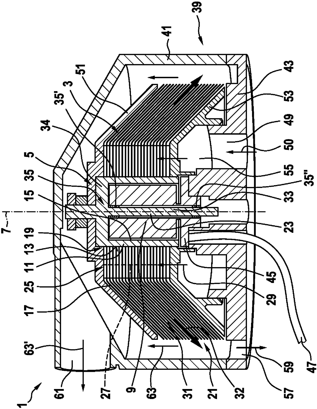
[0023] figure 1 A disc separator 1 for separating material from a material mixture is shown. The disk separator 1 is preferably designed as an oil separator for separating oil from the blow-by gas. The disc separator 1 has a separating device 3 and an electric motor 5 for rotationally driving the separating device 3 . The separating device 3 is coupled in a rotationally fixed manner to an electric motor 5 . The electric machine 5 is designed as an external rotor electric machine and has a radially inner stator 9 with respect to the rotational axis 7 of the electric machine 5 and an outer rotor 11 .

[0024] The rotor 11 here has a substantially cylindrical outer surface 13 . Furthermore, the rotor 11 has an inner side 15 which cooperates with the stator 9 according to the functional principle of known electrical machines.

[0025] The separating device 3 is fastened to the rotor 11 and extends outwards in radial direction from the rotor 11 . The stator 9 at least partiall...


PUM


Abstract

A plate separator (1) for separating a substance from a substance mixture, with a separator device (3) and an electric motor (5) for rotary driving of the separator device (3). The separator device (3) is coupled to the electric motor (5) in a rotationally fixed manner. The electric motor (5) is configured as an external rotor and has an inner-lying stator (9) and an outer-lying rotor (11) in theradial direction with respect to an axis of rotation (7) of the electric motor (5). The separator device (3) is fastened to the rotor (11) and extends outward from the rotor (11) in the radial direction. The stator (9) is arranged, as viewed in the axial direction with respect to the axis of rotation (7), at least partially overlapping with the separator device (3).

Description

technical field [0001] The invention relates to a disc separator for separating material from a material mixture, having the features stated in the preamble of claim 1 . Background technique [0002] Disc separators are often used as oil separators, for example, to separate oil from blow-by gases which, in particular, pass from the combustion chamber of the internal combustion engine into the crankcase of the internal combustion engine. For operating such disc separators, in particular electric motors are used. Such disc separators typically also have a separating device with a plurality of rotatable disc elements. The drive and the separating device of a disk separator of the type mentioned at the outset require a relatively large installation space. Furthermore, the drive device and the disconnecting device each need to be mounted separately, resulting in corresponding costs. [0003] The prior art is for example document DE 10 2009 036 476 A1. It relates to a centrifu...

Claims


Application Information

Patent Timeline
Patent Type & Authority Applications(China)
IPC IPC(8): B01D45/14F01M13/04B04B9/04B04B5/10
CPCB01D45/14B04B5/10B04B9/04F01M13/04B04B5/12B04B2005/125F01M2013/0422B04B9/08H02K7/16
Inventor S·里克特
Owner AUDI AG
Why Eureka
Try Eureka