Smashing device for refuse landfill

A landfill and crushing device technology, which is applied in transportation and packaging, chemical instruments and methods, and solid waste removal, etc. Ingenious design, multi-purpose power source, and volume reduction effect

Active Publication Date: 2018-10-23
贵州杉海沿环保科技有限责任公司
View PDF11 Cites 7 Cited by
  • Summary
  • Abstract
  • Description
  • Claims
  • Application Information

AI Technical Summary

Problems solved by technology

[0004] The present invention intends to provide a crushing device for landfills to solve the problems that the existing presses in landfills without pretreatment occupy a large area and the space of landfill pits cannot be fully utilized

Method used


Image

  • Smashing device for refuse landfill
  • Smashing device for refuse landfill
  • Smashing device for refuse landfill

Examples


Embodiment Construction

[0020] The following is further described in detail through specific implementation methods:

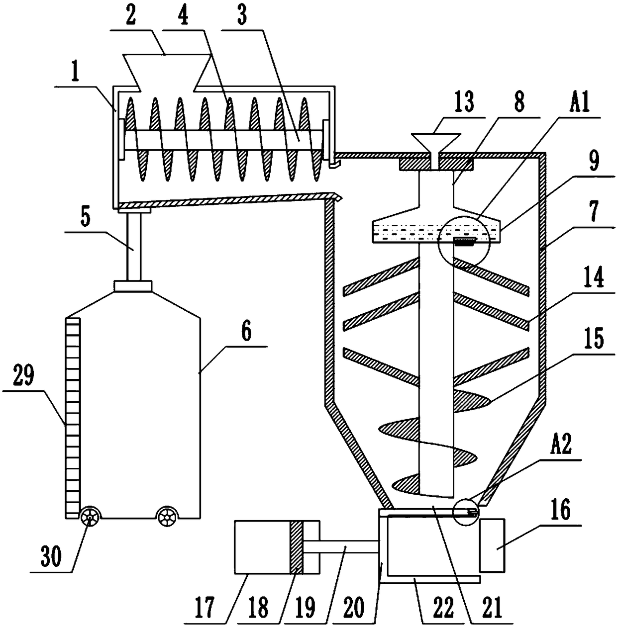
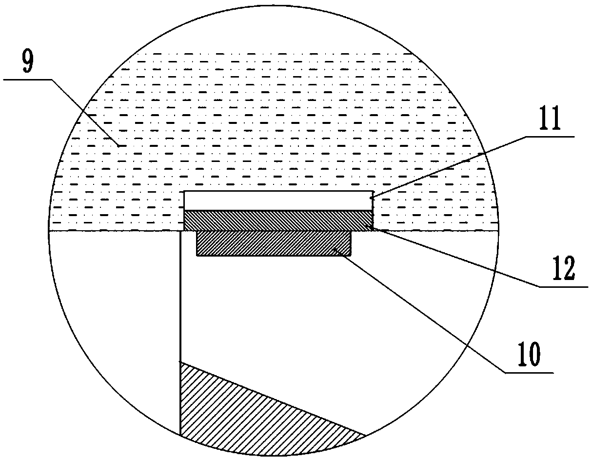
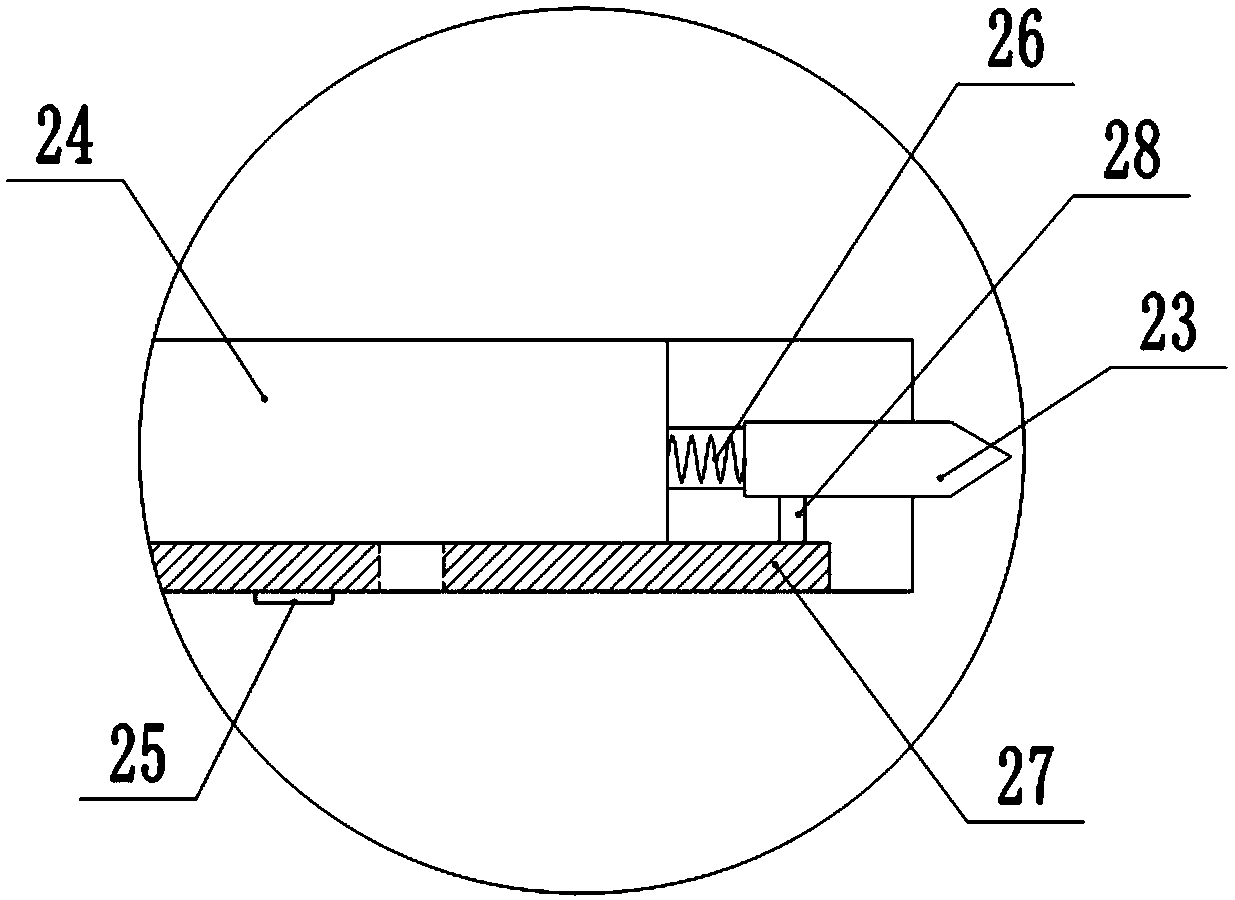
[0021] The reference signs in the drawings of the description include: feed box 1, feed hopper 2, rotating shaft 3, screw feed blade 4, liquid outlet pipe 5, storage tank 6, crushing box 7, crushing shaft 8, spray box 9 , the first magnet 10, the block 11, the second magnet 12, the hopper 13, the crushing blade 14, the spiral feeding blade 15, the fixed plate 16, the cylinder 17, the piston 18, the push rod 19, the vertical plate 20, the upper horizontal Plate 21, lower cross plate 22, cutting knife 23, liquid storage cavity 24, liquid outlet 25, support spring 26, slide bar 27, connecting rod 28, visible window 29, runner 30.

[0022] The embodiment is basically as attached figure 1 Shown: The crushing device for landfill, including feeding mechanism, crushing mechanism and briquetting mechanism. The feeding mechanism includes feeding box 1. The top left side of feeding box 1 is co...


PUM


Abstract

The invention relates to a smashing device for a refuse landfill. The device comprises a feeding mechanism, a smashing mechanism and a block pressing mechanism; the feeding mechanism comprises a feeding box, a rotating shaft is horizontally and rotatably connected into the feeding box, multiple spiral feeding blades are fixedly connected to the rotating shaft, the bottom wall of the feeding box communicates with a liquid discharge pipe, the end, away from the bottom wall of the feeding box, of the liquid discharge pipe communicates with a storage tank, the smashing mechanism comprises a smashing box, the top wall of the smashing box is vertically and rotatably connected with a smashing shaft, the upper portion of the smashing shaft is coaxially and fixedly connected with a spraying box, aspraying opening is formed in the bottom wall of the spraying box, a first magnet is arranged on the spraying opening, a check block is in sliding connection to the bottom wall of the spraying box, the bottom of the check block is fixedly connected with a second magnet attracted with the first magnet, a smashing blade and a spiral discharging blade are fixedly connected to the position, below thespraying box, on the smashing shaft, a discharging opening is formed in the lower portion of the spiral discharging blade, and the block pressing mechanism is located below the discharging opening. According to the device, garbage is pressed, and the waste pit space can be sufficiently used.

Description

technical field [0001] The invention relates to the technical field of garbage treatment, in particular to a pulverizing device for a garbage landfill. Background technique [0002] Garbage is a general term for solid and fluid substances that are not needed or useless. With the enhancement of social awareness of environmental protection, garbage is no longer dumped randomly, but is transported to landfills for disposal. The landfill is a place where garbage is piled up under the sanitary landfill method. The landfill is widely used in China because of its low cost and good sanitation. [0003] Garbage landfills generally use layered soil-covering methods to process garbage. After accumulating a layer of garbage and then covering it with a layer of loess, it is easy to reduce the pollution of garbage. At present, there are two ways to deal with garbage in landfills: biological method and physical and chemical method, but these two treatment methods are to directly operate ...

Claims


Application Information

Patent Timeline
Patent Type & Authority Applications(China)
IPC IPC(8): B09B3/00
CPCB09B3/00B09B3/21
Inventor 叶德刚
Owner 贵州杉海沿环保科技有限责任公司
Why Eureka
Try Eureka