Laser welding tool for engine hood of large aircraft

A technology of engine hood and laser welding, which is applied in the direction of laser welding equipment, welding equipment, welding equipment, etc., can solve the problems of part indentation, part pressure deformation, etc., and achieve the effects of convenient operation, shortened welding cycle, and labor saving

Pending Publication Date: 2018-10-23
CHENGDU HONGXIA TECH CO LTD
View PDF5 Cites 4 Cited by
  • Summary
  • Abstract
  • Description
  • Claims
  • Application Information

AI Technical Summary

Problems solved by technology

Since the profile pressing block is movable, each profile pressing block needs to be installed under the pressing screw respectively during work. Point or line contact with the part will cause indentation on the part, and in severe cases, the part will be partially deformed

Method used


Image

  • Laser welding tool for engine hood of large aircraft
  • Laser welding tool for engine hood of large aircraft
  • Laser welding tool for engine hood of large aircraft

Examples


Embodiment 1

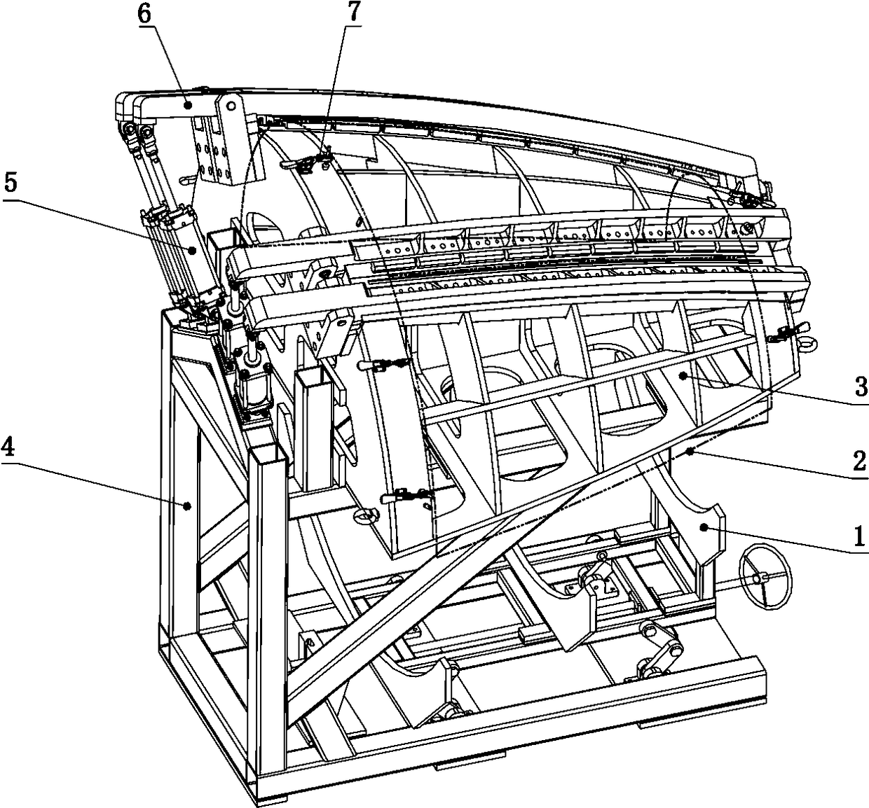
[0034] Such as figure 1 , 2 As shown, the present invention provides a kind of large-scale aircraft engine cover laser welding frock here, comprises mold body frame 3, support frame 4, cylinder 5, crossbeam 6, briquetting block 11, and mold body frame 3 is installed on the support frame 4, supports The frame 4 is also provided with a cylinder mount 8 , and the cylinder 5 is connected to the support frame 4 through the cylinder mount 8 . The mold body frame 3 is provided with a rotating seat 9, and the beam 6 is connected with the mold body frame 3 through a rotating shaft 10 on the rotating seat. One end of the crossbeam is connected with the piston rod of the cylinder, and the reciprocating motion of the cylinder 5 drives the crossbeam 6 to rotate; the other end of the crossbeam is provided with a hook, which is connected with the fixed buckle 14 on the mold body frame to lock the crossbeam 6 and the mold body frame 3.

[0035] The mold body frame is also provided with a f...

Embodiment 2

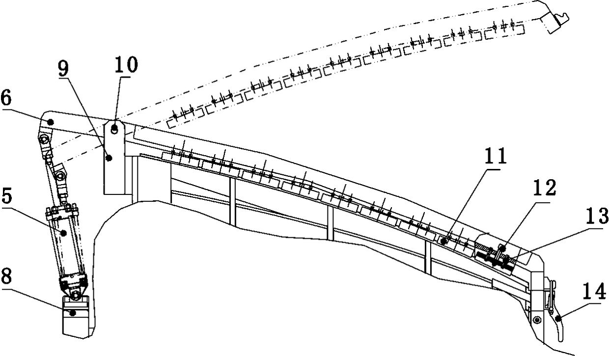
[0039] Such as figure 2 Shown is the working diagram of the beam. On the basis of the above, the present embodiment further optimizes the design: specifically, one end of the mold body frame is provided with a rotating seat 9, and the rotating seat 9 is provided with a rotating shaft 10, and the crossbeam 6 is connected with the mold body frame 3 through the rotating shaft 10. There is a hook at one end of the crossbeam, which is used to connect with the fixed buckle 14 at one end of the phantom frame, so as to realize the locking and fixing of the crossbeam 6 and the phantom frame 3. The other end of the beam is connected with the piston rod of the cylinder, and the cylinder 5 is installed on the support frame 4 . The reciprocating motion of the cylinder 5 drives the beam 6 to rotate around its center of rotation. When the cylinder 5 moves downward, it drives the crossbeam 6 to move upward around the rotating shaft, and the crossbeam 6 is opened and put into the mold body ...

Embodiment 3

[0042] Such as Figure 4 Shown is a schematic diagram of the phantom frame. This embodiment further optimizes the design on the basis of the foregoing embodiments: the profile of the phantom frame is set to be less than a semicircle, the maximum distance of the profile from the center line 16 is L, and the size of L remains at 80-100mm. The parts can be separated from the mold body surface smoothly when the parts are conveniently set up in this way, and the parts will not be scratched by frictional movement on the mold body surface.

[0043] The position of each component on the mold body frame is 0-0.1mm, and the limited position ensures the accurate installation of each component and improves the precision of the processing tooling.


PUM

PropertyMeasurementUnit
diameteraaaaaaaaaa
diameteraaaaaaaaaa

Abstract

The invention relates to a laser welding tool for an engine hood of a large aircraft. The laser welding tool comprises a supporting frame, a mold frame, a cylinder, a transverse beam and a mold bracket; the mold frame, the cylinder and the mold bracket are mounted on the supporting frame; the mold bracket is mounted at the bottom of the supporting frame, and the mold frame is arranged above the mold bracket correspondingly; and the cylinder is mounted on the supporting frame, the transverse beam is rotatably mounted on the mold frame through a rotating seat, one end of the transverse beam is connected with the cylinder to form a lever structure with the rotating seat as the pivot, and the other end of the transverse beam is detachably connected with the mold frame. The laser welding tool is simple in construction, reasonable in structure and convenient to use and is used for clamping and disassembling of parts in the laser welding process of the engine hood of the large aircraft, the laser welding tool is high precision, accurate in positioning and low in damage to the parts, and the transverse beam does not need to be disassembled repeatedly, the time is reduced, and the processing efficiency is high.

Description

technical field [0001] The invention belongs to the technical field of numerical control processing, and in particular relates to a laser welding tool for a large-scale aircraft engine cover. Background technique [0002] In the part processing of an aircraft engine shield, since the part material is 3.5mm titanium alloy, the diameter of the big end of the part is 1800mm, and the diameter of the small end is 970mm. Due to material limitations, the parts need to be molded separately and then welded together. The welding tooling of such parts generally adopts: molded tires to support the part profile; install beams at the weld position, and install compression screws on the beams; Acts on the profile briquetting block, enabling the briquetting block to compress the part. [0003] For laser welding of similar or similar parts, the current welding tooling has the following disadvantages: [0004] It is troublesome to disassemble and install the beam. At present, on similar...

Claims


Application Information

Patent Timeline
Patent Type & Authority Applications(China)
IPC IPC(8): B23K26/70B23K37/04
CPCB23K26/702B23K37/0443
Inventor 王勇游云洪刘伟军李春俊
Owner CHENGDU HONGXIA TECH CO LTD
Why Eureka
Try Eureka