Hydraulic direct drive type fin stabilizer fin rotating device

A direct-drive, fin stabilization technology, applied in the field of ships and marine engineering, can solve the problems of reducing the accuracy of transmission and servo control, and achieve the effect of improving the accuracy of transmission and servo control

Inactive Publication Date: 2018-10-23
WUHAN UNIV OF SCI & TECH
View PDF8 Cites 0 Cited by
  • Summary
  • Abstract
  • Description
  • Claims
  • Application Information

AI Technical Summary

Problems solved by technology

However, both of these two solutions require the shaft hole of the rotary vane hydraulic device to be sleeved on the fin shaft, and the movement and torque are transmitted through the cooperation between the hole and the shaft, which inevitably brings about the gap between the rotary vane hydraulic device and the fin shaft. Coaxiality error reduces the precision of transmission and servo control

Method used


Image

  • Hydraulic direct drive type fin stabilizer fin rotating device
  • Hydraulic direct drive type fin stabilizer fin rotating device

Examples


Embodiment Construction

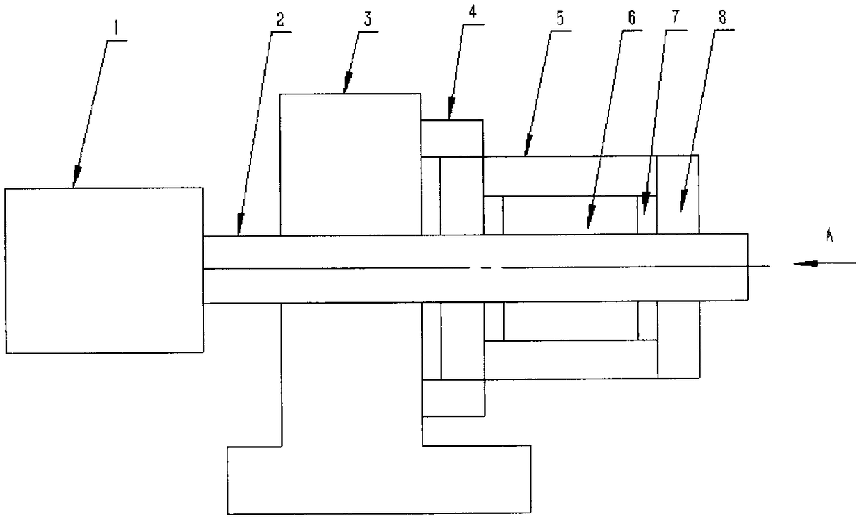
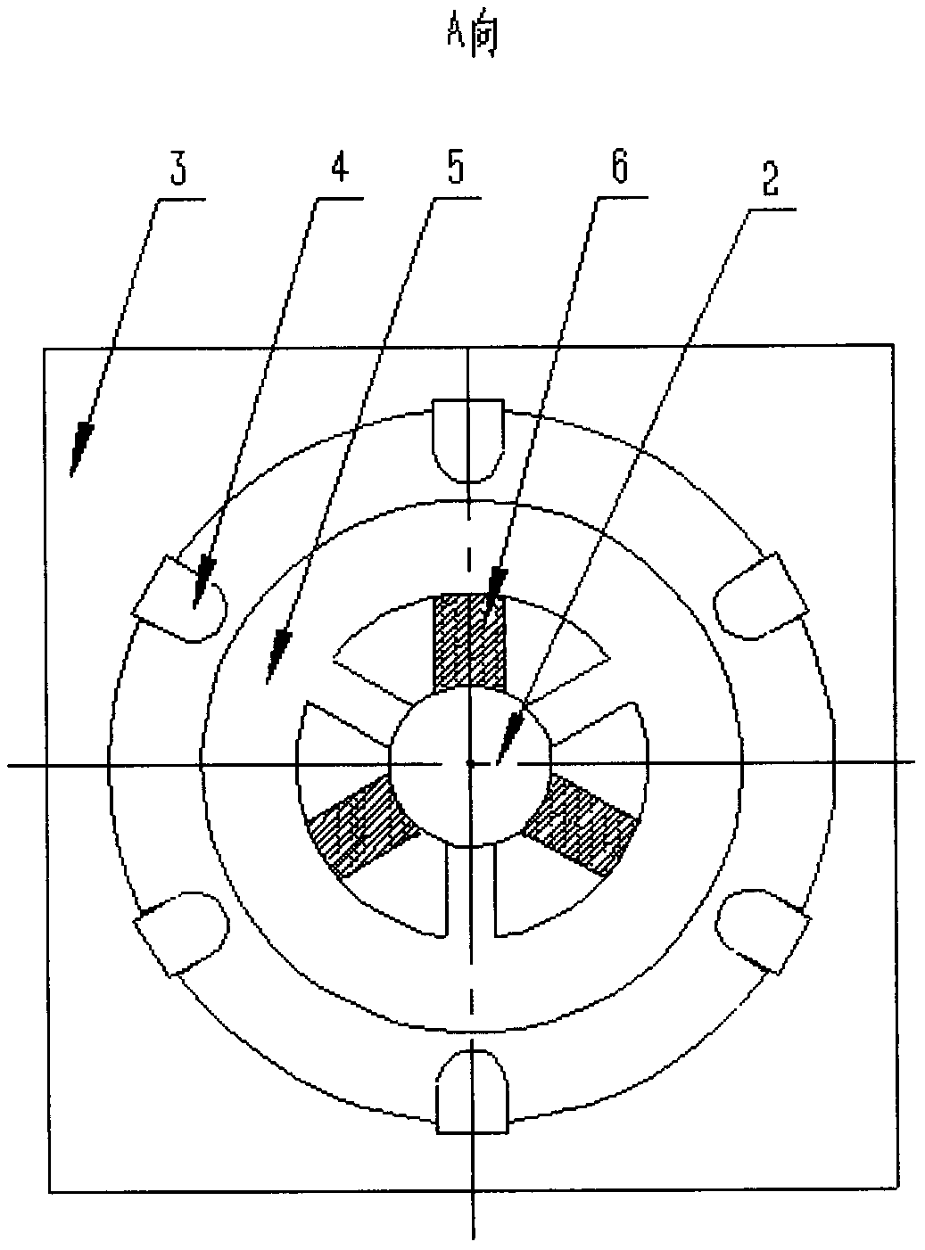
[0012] In order to make the object, technical solution and advantages of the present invention clearer, the implementation manner of the present invention will be further described in detail below in conjunction with the accompanying drawings.

[0013] An embodiment of the present invention provides a hydraulic direct drive fin stabilizer and fin rotation device, see figure 1 and figure 2 As shown, the device includes a stator with blades (including three blades evenly distributed along the circumferential direction), three fin shaft blades evenly distributed along the circumferential direction installed on the fin shaft, six stoppers, two end face seals , two end covers and some related connecting parts, such as screws, etc. from figure 2 It can be seen that the stator with blades, the end seal, and the fin shaft together form three oil chambers that are evenly distributed along the circumference, and the three fin shaft blades that are evenly distributed on the fin shaft...


PUM


Abstract

The invention discloses a hydraulic direct drive type fin stabilizer fin rotating device. The hydraulic direct drive type fin stabilizer fin rotating device structurally comprises a baffle block (4),a stator (5) with blades, two to four fin shaft blades (6), an end face seal (7) and an end cover (8). The fin shaft blades are evenly distributed and installed on a fin shaft in the peripheral direction and used for bearing oil pressure and outputting torque to the fin shaft and a fin wing (1) fixedly connected with the fin shaft. Blades with the equal number are evenly distributed on the statorwith the blades in the peripheral direction, and the blades and the end face seal jointly separate an oil cylinder to a high pressure cavity and a low pressure cavity. The baffle block is installed ona fin seat (3) and used for balancing the torque received by the stator with the blades. The hydraulic pressure is applied on the fin shaft blade to directly drive the fin shaft to rotate, and the problem of coaxiality error caused by connecting a shaft hole of a rotary vane type hydraulic device to the fin shaft in a sleeving mode is solved. Under the action of the hydraulic pressure, the coaxiality between the stator with blades and the fin shaft can be guaranteed automatically, and the coaxiality error between the stator with blades and the fin shaft caused by machining and installation error, gravity, wear, vibration and other factors can be avoided, and the transmission and servo control accuracy of the fin rotating device are improved.

Description

technical field [0001] The invention relates to a device for directly driving a stabilizer fin to rotate through hydraulic pressure, which belongs to the field of ships and marine engineering. Background technique [0002] The fin stabilizer is an important device to reduce the lateral roll of the ship and improve the stability of the ship. Among them, the fin rotating device is used to output swing and torque to the fin shaft and the fin wing fixedly connected with it. The common fin-rotating device usually adopts a transmission mechanism to convert the linear motion of the original moving parts such as the oil cylinder into reciprocating swing. The movement of the original moving parts (that is, the linear movement of the oil cylinder) is a complex nonlinear relationship, which increases the difficulty of servo control. For this reason, the patents "Marine Fin Stabilizer and Fin Angle Adjustment Device" (Application No.: CN201220117357.4) and "Ship Fin Stabilizer Fin Angl...

Claims


Application Information

Patent Timeline
IPC IPC(8): B63B39/06
CPCB63B39/06
Inventor 谢良喜罗刚吴攀峰
Owner WUHAN UNIV OF SCI & TECH
Why Eureka
Try Eureka