Flow adjusting valve

A flow regulating valve and valve seat technology, which is applied in the direction of valve lift, valve details, valve device, etc., can solve the problems of large coaxiality error, large winding of the drive shaft 78, and jamming of the drive shaft 78, and achieve the elimination of simultaneous Axial error, avoiding loosening problems, and avoiding the effect of screw rod jamming

Inactive Publication Date: 2014-05-14
ZHEJIANG SANHUA INTELLIGENT CONTROLS CO LTD
View PDF8 Cites 0 Cited by
  • Summary
  • Abstract
  • Description
  • Claims
  • Application Information

AI Technical Summary

Problems solved by technology

The processing and assembly of the various parts of the valve body will bring a large coaxiality error, so that there is a large coaxiality error between the drive shaft 78 and the discharge piston 130. Since the discharge piston 130 cannot shake in the radial direction, Thereby it is easy to cause the drive shaft 78 to be stuck;
[0006] Second, the rear part 94 and the middle part 96 are connected by thread fit. As the discharge piston 130 and the valve unit 40 move in the axial direction, the thread fit is prone to loosening, resulting in reliable axial positioning of the discharge piston 130. less sexual;
[0007] Third, the discharge piston 130 needs to be fixed in the sleeve 146 of the lower housing 60, and is restricted from rotating in the circumferential direction by the sleeve 146, so the discharge piston 130 needs to protrude from the valve unit 40 to a sufficient length to extend into the sleeve 146; this kind of structural design makes the drive shaft 78 matched with the discharge piston 130 also have a larger length, resulting in a large degree of winding of the drive shaft 78, and the coaxiality of the discharge piston 130 and the drive shaft 78 when assembled Difficult to guarantee, if the installation is biased, the resistance torque will be increased, and even the drive shaft 78 will be stuck;
[0008] Fourth, as mentioned above, the discharge piston 130 needs to protrude from the valve unit 40 to a sufficient length so as to penetrate into the sleeve 146, and accordingly, the drive shaft 78 and the lower housing 60 will have a relatively large gap in the axial direction. Large length, thus resulting in increased material costs
[0010] However, the flow regulating valve of this structure needs to set an annular limit groove on the inner wall of the installation cavity, and set a collar and a retaining ring in the limit groove to achieve a better technical effect. The bit structure is more complex

Method used


Image

  • Flow adjusting valve
  • Flow adjusting valve
  • Flow adjusting valve

Examples


Embodiment Construction

[0041] In order to enable those skilled in the art to better understand the technical solution of the present invention, the present invention will be further described in detail below in conjunction with the accompanying drawings and specific embodiments.

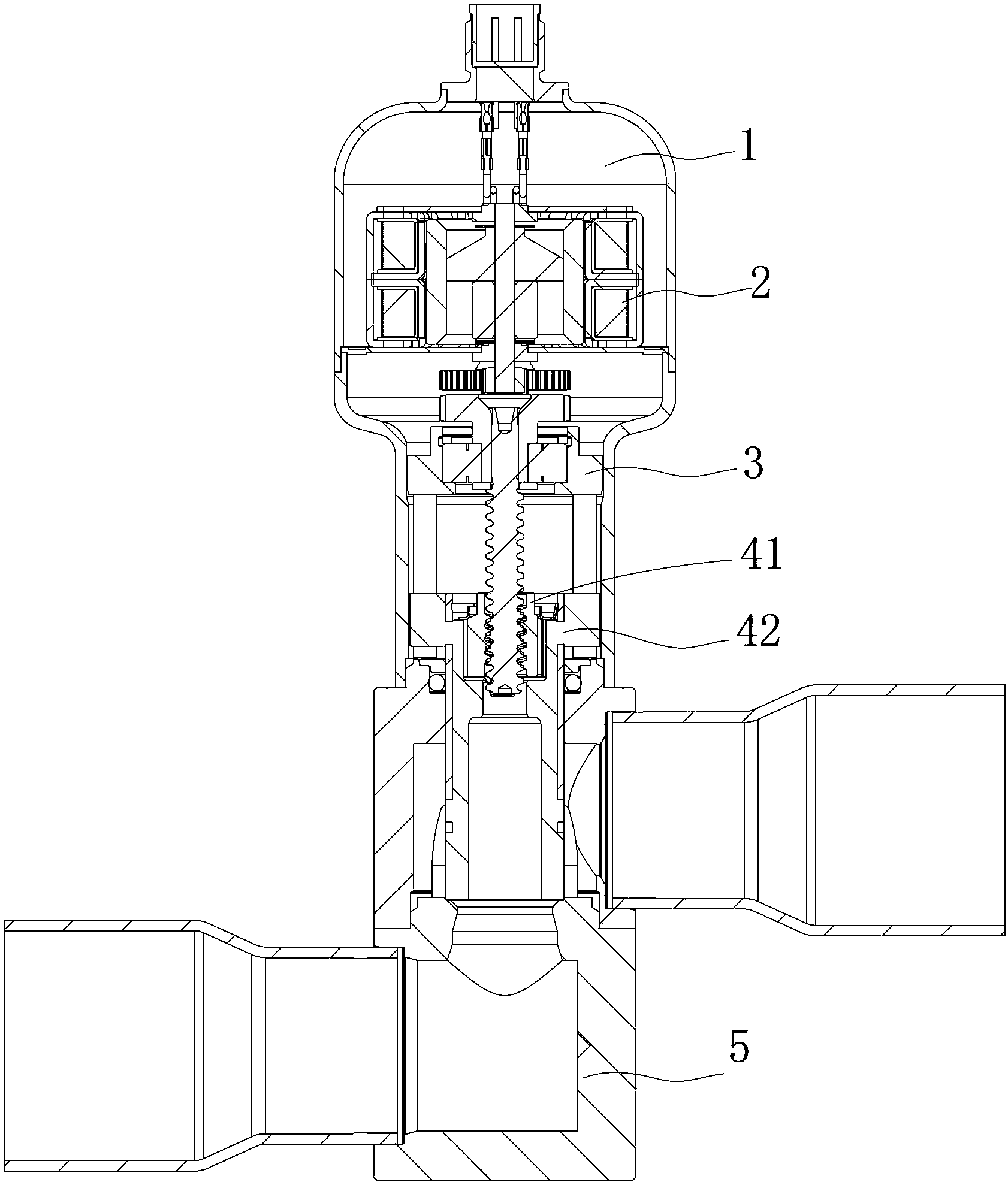
[0042] Please also refer to Figure 3 to Figure 7 , image 3 It is a schematic structural diagram of the flow regulating valve in the first embodiment of the present invention, Figure 4 for image 3 Schematic diagram of the structure of the stem part of the medium flow regulating valve, Figure 5 for Figure 4 Sectional view of the stem part in, Figure 6 for Figure 5 Exploded view of the middle valve stem component, Figure 7 for Figure 5 Partial enlarged view of part I of the middle valve stem part.

[0043] In the first embodiment, the flow regulating valve provided by the present invention includes a valve seat 5 and a housing 1 connected to the valve seat 5. The housing 1 is provided with a motor 2, and the...


PUM


Abstract

The invention discloses a flow adjusting valve which comprises a valve seat (5) and a shell (1) connected to the valve seat (5). A motor (2) is disposed in the shell (1). The motor (2) is connected with a screw (6) through the output shaft of the motor (2). The screw (6) is connected with a nut (41) in matched manner through threads. A valve rod (42) is connected to the nut (41). The valve rod (42) moves axially to adjust the openness of a valve opening of the valve seat (5). A mounting cavity (42a) is formed in the valve rod (42). The whole nut (41) or the lower portion of the nut (41) are matched into the mounting cavity (42a) along a radial gap. A clamp and stop portion (44) is disposed on the inner wall of the mounting cavity (42a). A clamp and stop part is disposed between the clamp and stop portion (44) and the nut (41), and the clamp and stop part is matched with the clamp and stop portion (44) to axially limit the nut (41). By the structure, the coaxiality error, caused by part machining and assembling, between the screw and the nut can be eliminated, and nut coaxial limit reliability can be increased.

Description

technical field [0001] The invention relates to the technical field of fluid control components, in particular to a flow regulating valve. Background technique [0002] The flow regulating valve is an important part of the refrigeration system, and it is another basic part of the four basic components of the refrigeration system except the evaporator, compressor and condenser. The working process of the flow regulating valve is generally: as the coil device is energized or de-energized, the valve needle adjusts the opening of the valve port, thereby adjusting the flow of the refrigerant. In addition, flow control valves are also widely used in other fluid control fields such as hydraulic systems and oil transportation. [0003] In the prior art, Chinese patent No. 200580023202.7 discloses a flow regulating valve; specifically, please refer to figure 1 and figure 2 , figure 1 It is a structural schematic diagram of a flow regulating valve in the prior art, figure 2 for...

Claims


Application Information

Patent Timeline
Patent Type & Authority Applications(China)
IPC IPC(8): F16K1/48F16K31/50
CPCF16K1/485F16K31/50
Inventor 不公告发明人
Owner ZHEJIANG SANHUA INTELLIGENT CONTROLS CO LTD
Why Eureka
Try Eureka