Folding propeller, power device and unmanned aerial vehicle

A power device and propeller technology, which is applied in the field of folding propellers, power devices and unmanned aerial vehicles, can solve the problems of excess weight of the carrier, limited mission equipment layout, etc.

Pending Publication Date: 2018-10-23
成都纵横大鹏无人机科技有限公司
View PDF10 Cites 4 Cited by
  • Summary
  • Abstract
  • Description
  • Claims
  • Application Information

AI Technical Summary

Problems solved by technology

The front-pull layout very restricts the layout of mission equipment: the front space is occupied by the power system and the rotation ra

Method used


Image

  • Folding propeller, power device and unmanned aerial vehicle
  • Folding propeller, power device and unmanned aerial vehicle
  • Folding propeller, power device and unmanned aerial vehicle

Examples


Embodiment 1

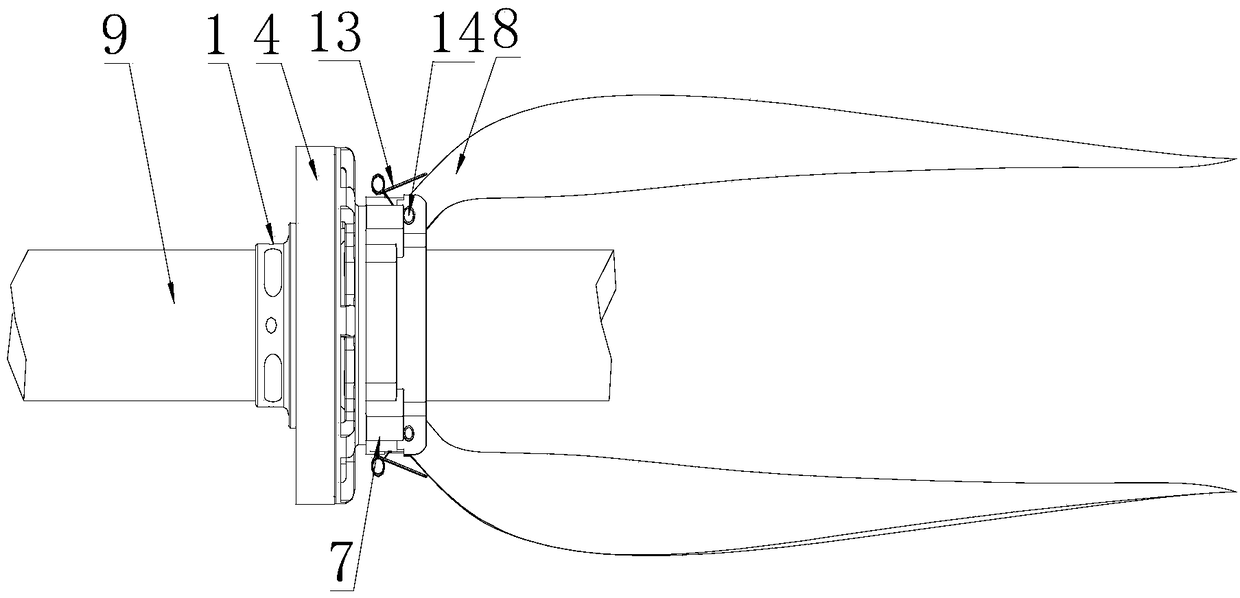
[0057] Such as Figure 1 to Figure 7 As shown, a foldable propeller includes a propeller seat 7 and a propeller blade 8 installed on the propeller seat 7, and also includes a pin shaft 14 and an elastic member 13, and one end of the propeller blade 8 passes through the pin shaft 14 and the propeller seat 7 hinged connection;

[0058] And when the paddle seat 7 is rotating, the motion direction of the mounting point of the pin shaft 14 on the paddle seat 7 is collinear with the axial direction of the pin shaft 14;

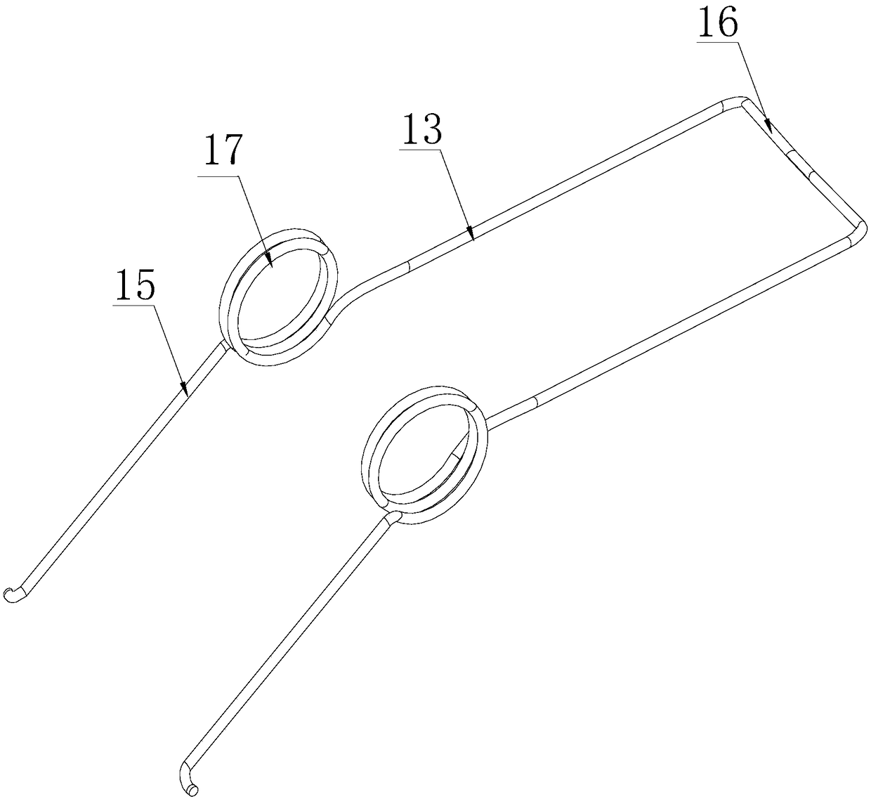
[0059] The two ends of the elastic member 13 act on the paddle seat 7 and the blade 8 respectively, and the elastic member 13 applies a torque to the blade 8 through the elastic recovery force, and the torque is used to force the blade 8 to rotate with the pin shaft. 14 is the rotation of the rotating shaft, and the direction of rotation is to make the free end of the blade 8 rotate to the axis of the propeller.

[0060] Specifically, in this solution, the installat...

Embodiment 2

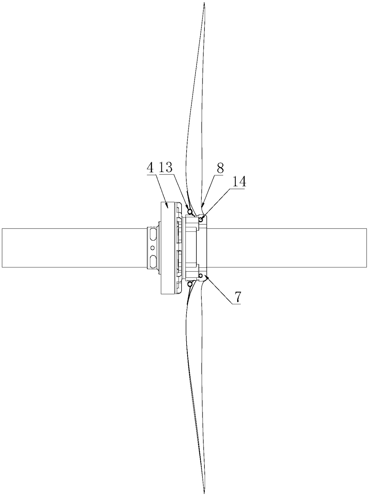
[0065] Such as Figure 1 to Figure 7 As shown, this embodiment is further limited on the basis of Embodiment 1: as a further technical solution of the above-mentioned folding propeller: the paddle seat 7 is in the shape of a ring, and the number of blades 8 It is multi-piece, and the paddle blades 8 are evenly distributed on the paddle seat 7 in an annular shape;

[0066] Each paddle 8 is hingedly connected to the paddle seat 7 through a pin shaft 14 , and an elastic member 13 is arranged between each paddle 8 and the paddle seat 7 . This solution can avoid the eccentric force generated by the propeller in the working process and affect the stable flight of the UAV. At the same time, the above solution enables each blade 8 to retract through the corresponding elastic member 13 when the propeller speed decreases.

[0067] As the specific setting form of the propeller: the paddle seat 7 includes a circular seat body and a plurality of mounting parts for realizing the installat...

Embodiment 3

[0078] Such as Figure 1 to Figure 7 As shown, the present embodiment provides a power device 10, including a driving part and a propeller connected to the output end of the driving part, and the propeller is any foldable propeller provided in any one of the above embodiments. In summary, this solution provides a power unit 10 in which the propeller blade 8 can be recovered by itself after the propeller speed is reduced. This power unit 10 is not only conducive to the safety of the propeller when the UAV lands; at the same time, the recovery of the propeller blade 8 does not depend on external Energy input; at the same time, due to the characteristics of simple structure, light weight and high reliability of the propeller, the power device 10 using the propeller also has the characteristics of simplicity, light weight and high reliability.


PUM


Abstract

The invention discloses a folding propeller, a power device and an unmanned aerial vehicle. The folding propeller comprises a propeller seat and propeller blades mounted on the propeller seat, and further comprises pin shafts and an elastic piece; one ends of the propeller blades are connected with the propeller seat through the pin shafts in a hinged mode; and the two ends of the elastic piece act on the propeller seat and the propeller blades correspondingly. The folding propeller is used for the power device, the power device is used for the unmanned aerial vehicle, according to the structural design of the propeller, the propeller blades can be retracted automatically after the rotating speed of the propeller is decreased, in this way, the safety of the propeller during landing of theunmanned aerial vehicle is facilitated, and meanwhile, retracting of the propeller blades does not depend on external energy input; and meanwhile, the propeller is simple in structure, small in mass and high in reliability.

Description

technical field [0001] The invention relates to the field of aviation flight equipment, in particular to a folding propeller, a power device and an unmanned aerial vehicle. Background technique [0002] In the prior art, unmanned aerial vehicles are widely used in a wide range of fields, such as monitoring, reconnaissance and surveying and mapping. At present, UAVs can be roughly divided into fixed-wing UAVs, unmanned helicopters, multi-rotor UAVs and compound-wing UAVs. Fixed-wing UAVs and compound-wing UAVs generate aerodynamic lift through their wings, which are superior to rotary-wing UAVs in terms of range, speed, and ceiling, and are more suitable for monitoring, reconnaissance, mapping and other tasks. [0003] The power layout of fixed-wing UAVs and compound-wing UAVs can be divided into: front pull, waist push and tail push. The front-pull layout greatly limits the arrangement of mission equipment: the front space is occupied by the power system and the rotation r...

Claims


Application Information

Patent Timeline
IPC IPC(8): B64C1/30B64C27/32B64C27/12B64C27/08
CPCB64C1/30B64C27/08B64C27/12B64C27/32
Inventor 王利光田裕夫付鹏
Owner 成都纵横大鹏无人机科技有限公司
Why Eureka
Try Eureka