Wing folding and unfolding mechanism for cylindrical launching unmanned aerial vehicle

A technology of a wing folding and unfolding mechanism, applied in the field of unmanned aerial vehicles, can solve the problems such as the inability to solve the sliding friction resistance of the installation gap, the reliability of the unfolding process is deteriorated, and the flight stability is affected, so as to improve the flight reliability and environmental dependence. The effect of small sex and simple structure

Pending Publication Date: 2018-10-23
GENERAL ENG RES INST CHINA ACAD OF ENG PHYSICS
View PDF9 Cites 15 Cited by
  • Summary
  • Abstract
  • Description
  • Claims
  • Application Information

AI Technical Summary

Problems solved by technology

[0006] Most of the existing wing folding and unfolding mechanisms have no wing surface synchronization mechanism, and the deployment synchronization is only guaranteed by torsion springs and friction matching. The synchronization is poor and affects flight stability.
[0007] In addition, most folding mechanisms have plane sliding friction between the airfoils and between the airfoil and the body during the unfolding process, which cannot solve the contradiction between the installation gap and the sliding friction resistance during the unfolding process.
When the installation gap increases, the friction in the unfolding process decreases, but the sloshing of the airfoil increases after the deployment, which is not conducive to flight control; when the installation gap decreases, the friction in the deployment process increases, the deployment time increases, and the reliability of the deployment process increases. become worse

Method used


Image

  • Wing folding and unfolding mechanism for cylindrical launching unmanned aerial vehicle
  • Wing folding and unfolding mechanism for cylindrical launching unmanned aerial vehicle
  • Wing folding and unfolding mechanism for cylindrical launching unmanned aerial vehicle

Examples


Embodiment Construction

[0042] The present invention will be further described below in conjunction with accompanying drawing:

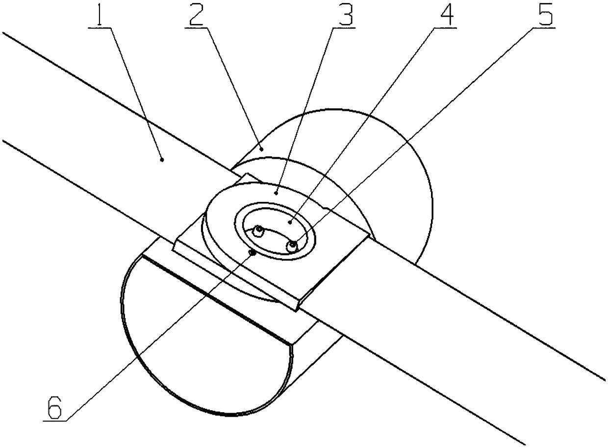
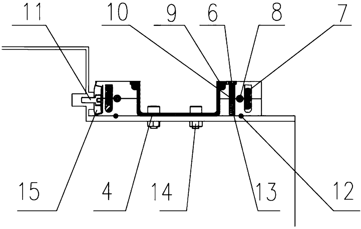
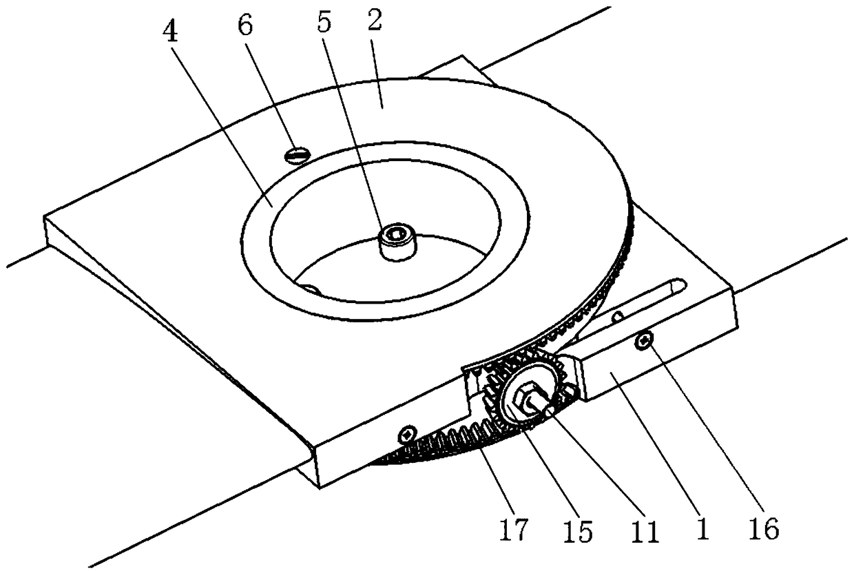
[0043] Such as Figure 1-Figure 5 As shown, the barrel-type launching UAV wing folding and unfolding mechanism is used to rotate and unfold or fold the upper wing 3 and the lower wing 1 on the UAV fuselage 2, and the lower wing 1 is arranged on the upper wing 3 and the unmanned Between the fuselage 2, the wing folding and unfolding mechanism includes:

[0044] A torsion spring 7 for twisting and unfolding the upper wing 3 and the lower wing 1 stored overlappingly, one end of the torsion spring 7 is connected to the upper wing 3, and the other end of the torsion spring 7 is connected to the lower wing 1;

[0045] When the upper wing 3 and the lower wing 1 are unfolded, a plurality of airfoil balls 8 that make the upper wing 3 and the lower wing 1 come into relative rolling contact; Ball groove 19, a part of the airfoil ball 8 rolls in the ball groove 19 of the upper wing 3...


PUM


Abstract

The invention discloses a wing folding and unfolding mechanism for a cylindrical launching unmanned aerial vehicle. A torsion spring serves as wing surface expanding power, the mechanism is simple andreliable, and dependence on the environment is small; a bevel gear serves as a synchronous mechanism for the wing surface expanding process, the mechanism is simple and small in size, a wing surfacecan be unfolded completely and synchronously, and the flight reliability of the unmanned aerial vehicle is improved; a locking pin serves as a locking mechanism after the wing surface is expanded, thestructure is simple and small in size, reliability is good, a locking pin cap is designed, thus it is ensured that a wing can be rapidly folded after the unmanned aerial vehicle is retracted, and retracting of the unmanned aerial vehicle is competed; different balls serve as the contact form between motion interfaces, the friction resistance of the opening process is reduced, and rapidity of theopening process is ensured; and the overall folding mechanism is high in integration degree, simple, small in size, easy to assemble, and easy and convenient to operate, and the demands of the cylindrical launching unmanned aerial vehicle for wing folding are met.

Description

technical field [0001] The invention belongs to the technical field of unmanned aerial vehicles, and in particular relates to a wing folding and unfolding mechanism for a barrel-type launching unmanned aerial vehicle. Background technique [0002] Compared with other fixed-wing UAVs, the barrel-launched folding-wing UAV has many advantages. It is small in size, can be carried by an individual soldier, can quickly enter the combat zone, and has flexible tactics and strong maneuverability. It is suitable for anti-terrorism and urban warfare. [0003] At present, the U.S. military has individual loitering missiles that use a barrel-type launch folding-wing UAV solution. Among them, the "Switchblade" series has a barrel bomb with a total weight of less than 3kg and a warhead of about 320g. Vehicle-based. The more mature product of the Israeli "Hero" series of short-range loitering missiles is the "Hero" 30, which is as powerful as the "Switch Knife". It also adopts a barrel-typ...

Claims


Application Information

Patent Timeline
Patent Type & Authority Applications(China)
IPC IPC(8): B64C3/56
CPCB64C3/56
Inventor 赵昕亮钱立新卢永刚孙传杰冯高鹏朱永清李永泽陶江源
Owner GENERAL ENG RES INST CHINA ACAD OF ENG PHYSICS
Why Eureka
Try Eureka