Engine waste heat power recovery system and method

A recovery system and recovery method technology, applied in the field of engines, can solve problems such as not being environmentally friendly

Inactive Publication Date: 2018-10-23
阮家文
View PDF3 Cites 2 Cited by
  • Summary
  • Abstract
  • Description
  • Claims
  • Application Information

AI Technical Summary

Problems solved by technology

[0003] However, the main engine often produces a large amount of hot air during operation, and these hot air are all discarded under the curr...

Method used


Image

  • Engine waste heat power recovery system and method
  • Engine waste heat power recovery system and method
  • Engine waste heat power recovery system and method

Examples


Embodiment Construction

[0020] The present invention will be described in detail below in conjunction with the accompanying drawings and embodiments.

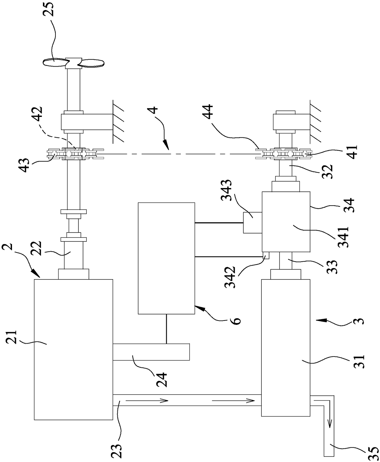
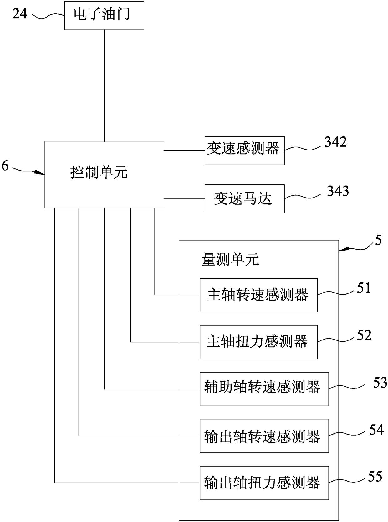
[0021] refer to figure 1 , 2 , 3, an embodiment of the engine waste heat power recovery system and method of the present invention, the engine waste heat power recovery system includes a main power unit 2, an auxiliary power unit 3, a transmission unit 4, a measurement unit 5, and a control Unit 6.

[0022] The main power unit 2 includes a main engine 21, a main shaft 22 connected and driven to rotate by the main engine 21, a heat pipe 23 connected to the main engine 21, and a control unit 6 connected to the main engine 21 and electrically connected To adjust the electronic throttle 24 of the fuel intake of the main engine 21 .

[0023] The auxiliary power unit 3 includes a Stirling engine 31 connected to the heat pipe 23, an output shaft 32 that is rotated in conjunction with the Stirling engine 31, and an auxiliary shaft that is connected and dri...


PUM


Abstract

An engine waste heat power recovery system comprises a main power unit, an auxiliary power unit and a transmission unit. The main power unit comprises a main engine, a spindle connected with the mainengine and driven by the main engine to rotate, and a heat conducting tube connected with the main engine. The auxiliary power unit comprises a Stirling engine connected with the heat conducting tube,and an output shaft linked with the Stirling engine to rotate. The transmission unit is arranged between the spindle and the output shaft to transmit the torsion of the output shaft to the spindle. Through arrangement of the main power unit, the auxiliary power unit and the transmission unit, waste heat of the main engine can drive the Stirling engine to provide auxiliary torsion, thus the effectof waste heat power recovery is achieved, and the purpose of the engine waste heat power recovery system can be achieved indeed.

Description

technical field [0001] The invention relates to an engine, in particular to an engine waste heat power recovery system and method. Background technique [0002] An existing power system for driving a ship's propeller to rotate includes a main engine, and a main shaft driven by the main engine and connected to the ship's propeller. By driving the main engine to operate, the main shaft can be driven The ship's propeller turns, which in turn has the effect of moving the ship. [0003] However, the main engine often produces a large amount of hot air during operation, and these hot air are all discarded under current usage conditions. Since heat is also a kind of energy, if it is directly discarded, it is not only a pity, but also not environmentally friendly. Contents of the invention [0004] The object of the present invention is to provide an engine waste heat power recovery system and method. [0005] The engine waste heat power recovery system of the present invention ...

Claims


Application Information

Patent Timeline
IPC IPC(8): F02G5/02F02G1/043F02G1/06F16H37/12B63H23/06
CPCB63H23/06F02G1/043F02G1/06F02G5/02F16H37/12Y02T10/12
Inventor 阮家文魏益堂
Owner 阮家文
Why Eureka
Try Eureka