Heat dissipation device for oil pump

A heat dissipation device and oil pump technology, which is applied in the field of heat dissipation devices of oil pumps, can solve the problems that the relative position of the oil pump and the oil pump motor controller is not easy to determine, the design of the connecting pipeline is complicated, and the pipeline is aging and leaking, so as to improve the reliability of the system , Easy installation, save the effect of connecting pipelines

Active Publication Date: 2018-10-23
CHINA NORTH VEHICLE RES INST
View PDF8 Cites 3 Cited by
  • Summary
  • Abstract
  • Description
  • Claims
  • Application Information

AI Technical Summary

Problems solved by technology

With the development and application of new technologies such as high-power-density engines, electromechanical hybrid transmissions, and electric transmissions, the layout of vehicles is becoming more and more compact, and the relative positions of the oil pump and the oil pump motor controller are not easy to determine, resulting in the gap between the oil cooler and the water cooling plate. The design of the connecting pipeline is complicated, the resistance of the water system becomes larger, and it is easy to form air resistance, causing the system to overheat; in addition, after a long period of use, the possibility of pipeline aging and leakage will increase, which is a common failure in the system. Among them, the proportion of failure to work due to pipeline leakage is as high as 40% to 50%.

Method used


Image

  • Heat dissipation device for oil pump
  • Heat dissipation device for oil pump
  • Heat dissipation device for oil pump

Examples


Embodiment Construction

[0036] In order to better understand the present invention, the technical solution of the present invention will be further described in detail below in conjunction with the accompanying drawings.

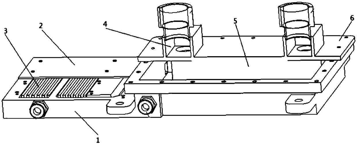
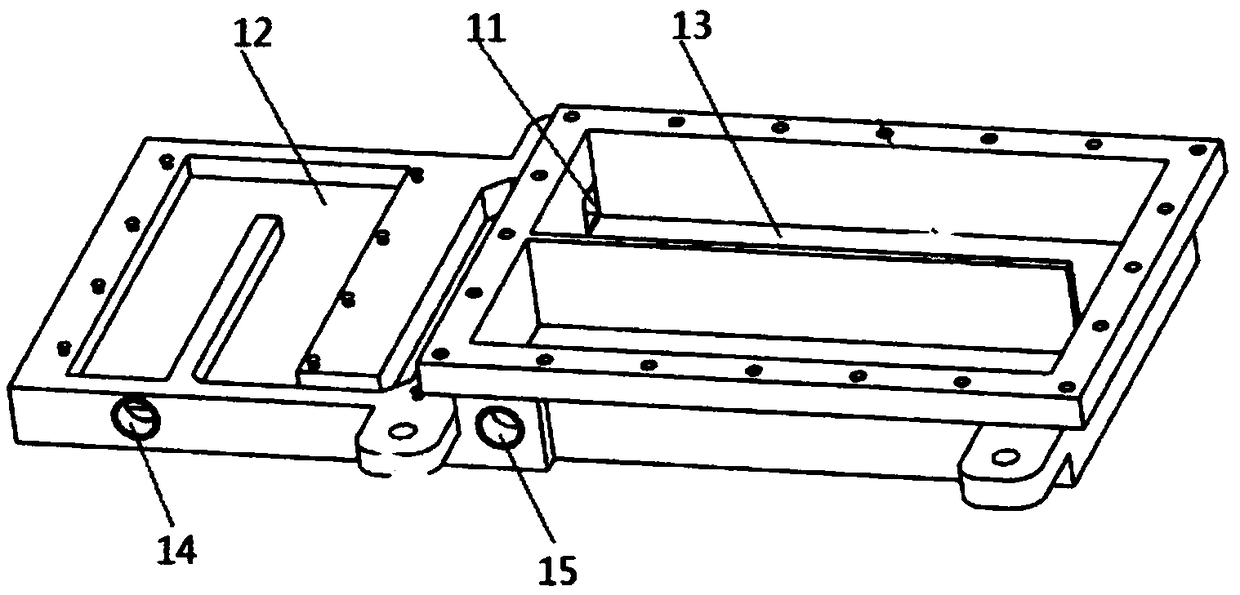
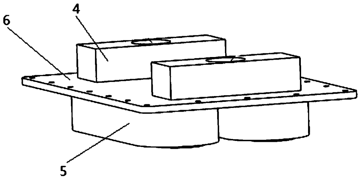
[0037] Such as Figure 1 to Figure 5 As shown, the heat dissipation device for the oil pump provided by the present invention, the oil pump includes: a motor and a hydraulic oil tank, the motor includes: a motor controller IGBT module 7, and the heat dissipation device is arranged on the motor controller IGBT module 7 Below, the IGBT module 7 includes: a control board 7-4, a drive board 7-3, a gate plate (7-2) and an IGBT element 7-1 arranged in sequence; the heat dissipation device includes: a horizontally arranged groove 1 and an oil component located above the tank 1 and connected to the hydraulic oil tank; the tank 1 is a rectangular water-cooled tank composed of left and right water tanks; the left water-cooled tank 12 is arranged on the IGBT element 7-1 The lower end, so tha...


PUM


Abstract

The invention relates to a heat dissipation device for an oil pump. The oil pump comprises a motor and a hydraulic oil tank. The motor comprises a motor controller IGBT module. The heat dissipation device is arranged on the lower portion of the motor controller IGBT module. The IGBT module comprises a control panel, a driving plate, a gate pole plate and an IGBT element. The heat dissipation device comprises a groove and an oil fluid assembly. The groove is a rectangular water-cooling groove composed of a left water tank and a right water tank. The left water-cooling tank is arranged at the lower end of the IGBT element, and the right water-cooling tank is arranged on the lower portion of the oil fluid assembly. According to the heat dissipation device, integrated consideration of the IGBTelement and hydraulic oil fluid heat dissipation is put forward for the first time, the function of an oil cooler is achieved simultaneously on the basis of traditional water-cooling heat dissipation, the characteristic of the low cold source temperature of the heat dissipation device is fully utilized, a cooling liquid flowing out of the heat dissipation device can still serve as a cold source of an oil-water heat exchanger, one path of circulating water is reduced, and the high integration and lightweight effects are achieved.

Description

technical field [0001] The invention relates to the field of vehicle heat dissipation, in particular to a heat dissipation device for an oil pump. Background technique [0002] At present, the heat dissipation of motors and motor controllers is particularly important in vehicle design. In the traditional design concept, the heat dissipation of oil and electricity is considered separately. For example, the heat dissipation of the oil pump motor oil and the heat dissipation of the IGBT components of the motor controller are carried out through the oil cooler and the water cooling plate respectively. If the two share one refrigerant, then It is necessary to connect the oil cooler and the water cooling plate through pipelines. With the development and application of new technologies such as high-power-density engines, electromechanical hybrid transmissions, and electric transmissions, the layout of vehicles is becoming more and more compact, and the relative positions of the oi...

Claims


Application Information

Patent Timeline
Patent Type & Authority Applications(China)
IPC IPC(8): F04B53/08H02K9/19
CPCH02K9/19F04B53/08
Inventor 刘洋邵春鸣张佳卉石军曹元福赵春伟刘建锋周丽刘江权
Owner CHINA NORTH VEHICLE RES INST
Why Eureka
Try Eureka