
Centrifugal pendulum device and torsional vibration damper comprising such a centrifugal pendulum device

A technology of centrifugal pendulum and support device, applied in spring/shock absorber, rotational vibration suppression, vibration suppression adjustment, etc., can solve the problems of reducing the weight of rotation or torsional vibration, weight of pendulum weight, etc.

Active Publication Date: 2018-10-23
BORGWARNER INC
View PDF9 Cites 3 Cited by
  • Summary
  • Abstract
  • Description
  • Claims
  • Application Information

AI Technical Summary

Problems solved by technology

This solution, although effective, has the disadvantage that the pendulum weight must have relatively large dimensions in order for the pendulum weight to have the weight necessary to reduce rotational or torsional vibrations

Method used


Image

  • Centrifugal pendulum device and torsional vibration damper comprising such a centrifugal pendulum device
  • Centrifugal pendulum device and torsional vibration damper comprising such a centrifugal pendulum device
  • Centrifugal pendulum device and torsional vibration damper comprising such a centrifugal pendulum device

Examples


Embodiment Construction

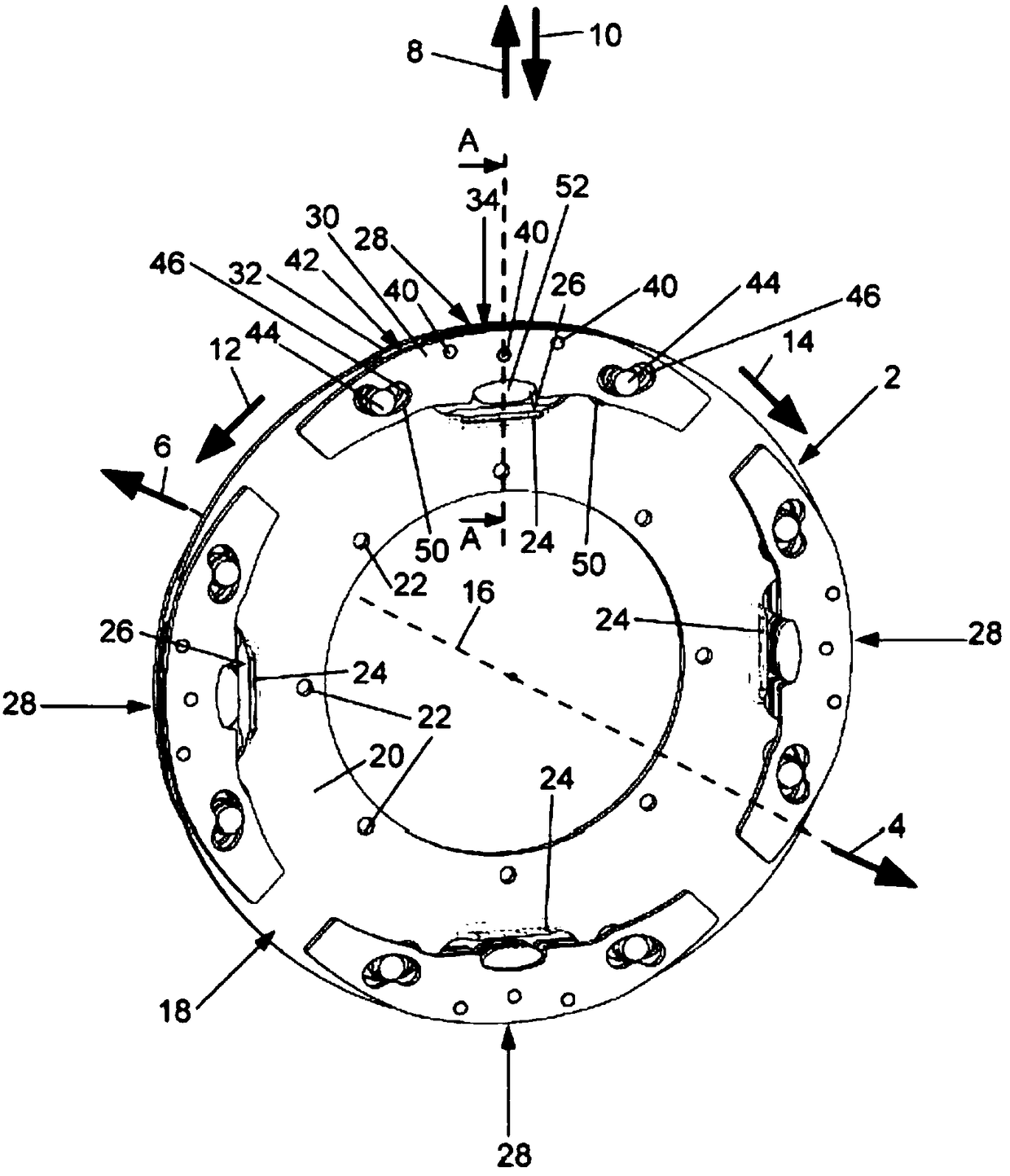
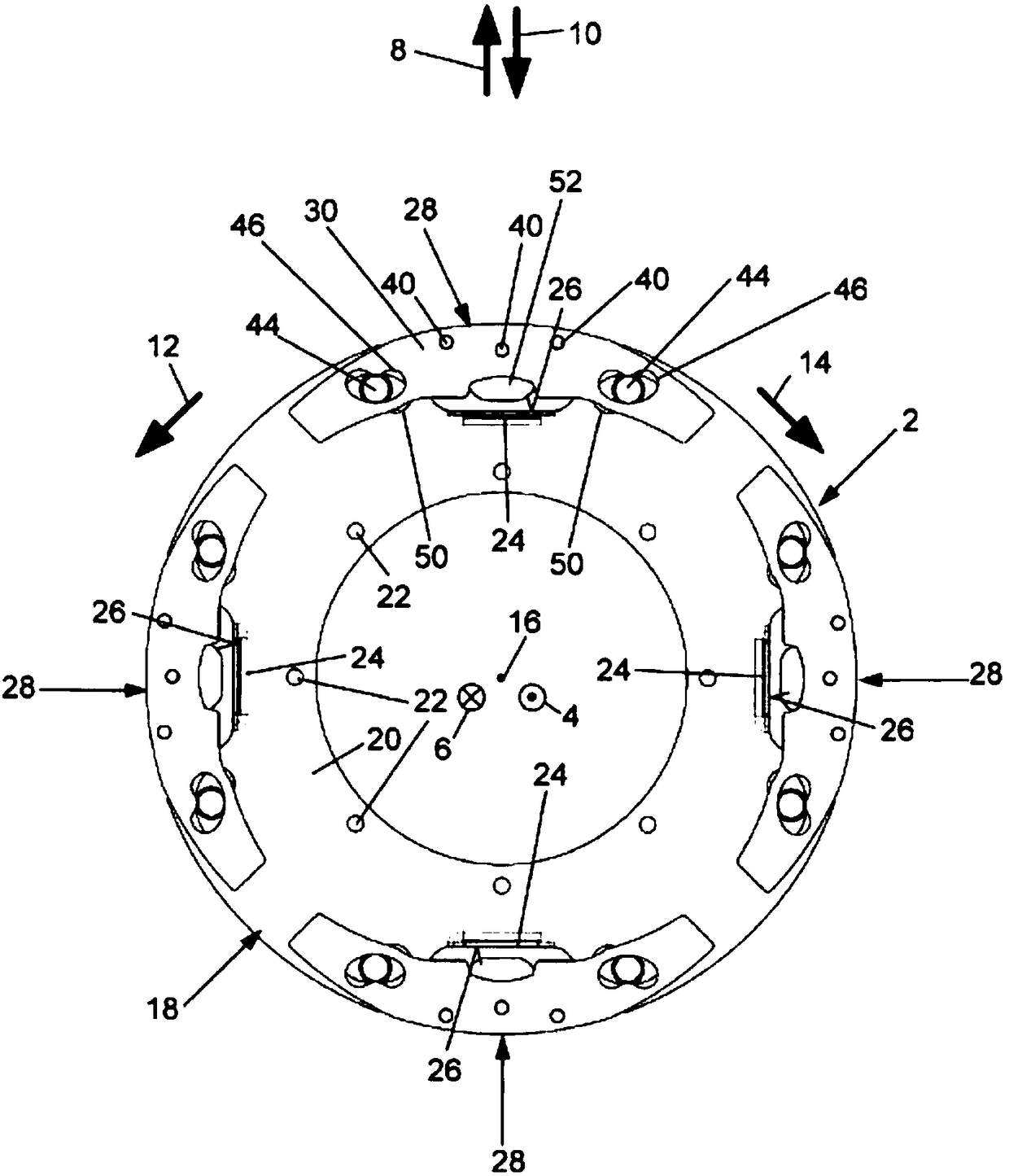
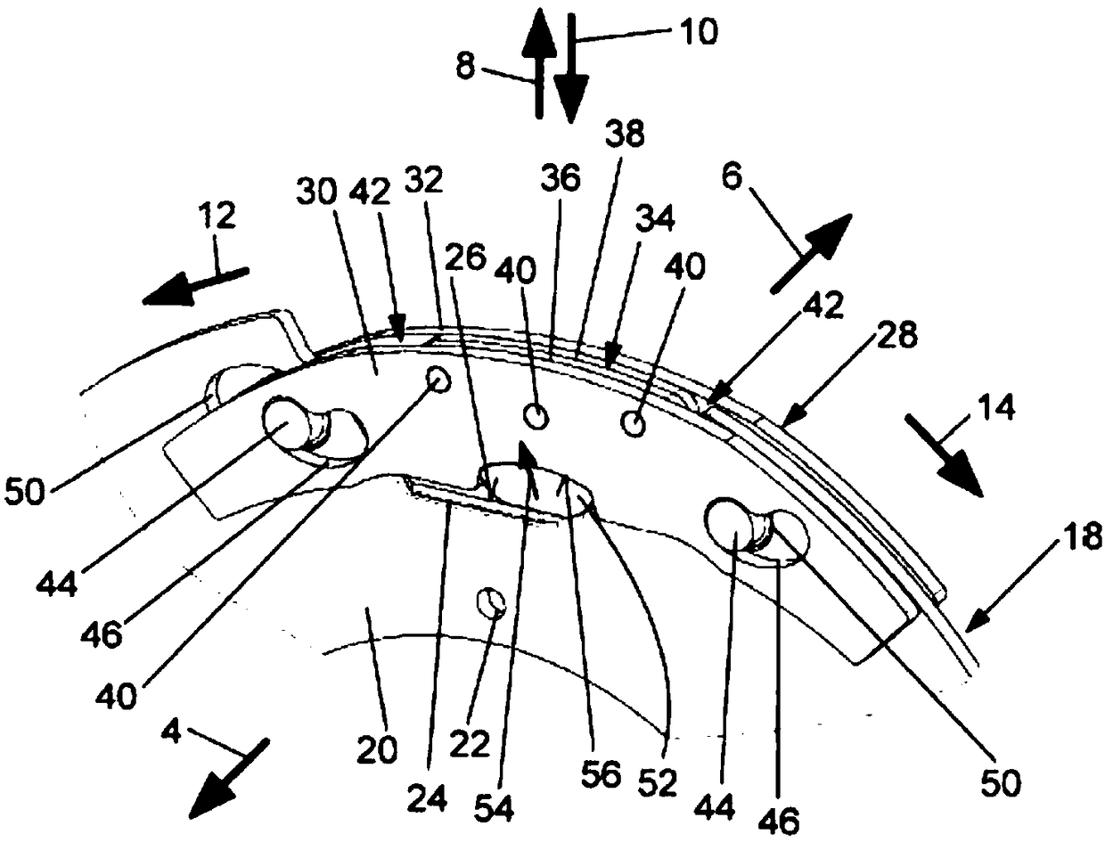
[0037] figure 1 and 2 A centrifugal pendulum device 2 for a drive train of a motor vehicle is shown. In the drawings, the mutually opposite axial directions 4, 6 of the centrifugal pendulum device 2, the mutually opposite radial directions 8, 10 and the mutually opposite circumferential directions 12, 14 of the centrifugal pendulum device 2 are shown according to corresponding arrows, for which the centrifugal pendulum device 2 Alternatively, the pendulum carriage, which will be described in detail below, rotates about a rotational axis 16 extending in the axial direction 4 , 6 .

[0038] The centrifugal pendulum device 2 has a pendulum carriage 18 rotatable about an axis of rotation 16 . The pendulum carriage 1 extends around its periphery in the circumferential direction 12, 14 and is plate-like or disk-shaped, more precisely ring-shaped. Inner extension. The pendulum bracket 18 essentially consists of a load-bearing section 20, on which there are fixed openings 22 distr...


PUM


Abstract

The present invention relates to a centrifugal pendulum device (2) comprising a rotatable pendulum mass carrier (18) and at least one pendulum mass (28), which is arranged thereon to be moveable between two end positions relative to the pendulum mass carrier (18) due to at least one guide element (44) which extends in guide means (46, 48, 50) in the pendulum mass carrier (18) and the pendulum mass(28), wherein a damping element (52) is arranged on the pendulum mass (28) via which the pendulum mass (28) is supported or supportable on the pendulum mass carrier (18) before reaching at least oneof the end positions, preferably both end positions. In addition, the present invention relates to a torsional vibration damper comprising such a centrifugal pendulum device (2).

Description

technical field [0001] The invention relates to a centrifugal pendulum device with at least one rotatable pendulum bracket and at least one pendulum counterweight arranged on the pendulum bracket, the pendulum counterweight passes through at least one pendulum counterweight along the pendulum bracket and the pendulum counterweight The heavy guide groove-extended guide element moves relative to the pendulum carriage between two final positions. Background technique [0002] Various so-called centrifugal pendulum devices are known in practice, which have a rotatable pendulum carriage and at least one pendulum counterweight arranged on the pendulum carriage. At least one pendulum weight is moved relative to the pendulum bracket between two end positions by means of at least one guide element extending along the guide groove of the pendulum bracket and the pendulum weight, so that the drive will be driven similarly to a torsional shock absorber Minimize or reduce torsional or r...

Claims


Application Information

Patent Timeline
IPC IPC(8): F16F15/14F16F15/131
CPCF16F15/131F16F15/14F16F15/145F16F15/13128
Inventor O·格罗内贝格
Owner BORGWARNER INC
Learn More