Broadband vortex-induced vibration piezoelectric energy collector installed on high-speed railway
A vortex-induced vibration and piezoelectric energy technology, which is applied in the fields of wind power generation and energy collection, can solve the problems of inappropriate energy collection of high-speed train tracks, and achieve the effect of providing energy collection bandwidth, simple structure and prolonging service life.
- Summary
- Abstract
- Description
- Claims
- Application Information
AI Technical Summary
Problems solved by technology
Method used
Image
Examples
Embodiment 1
[0063] The motion of each component is as follows figure 1 shown, figure 1 In the figure, the section line and the solid line are the piezoelectric energy harvester; the straight arrow represents the outside high-speed airflow entering the piezoelectric energy harvester; the rotating curved arrow represents the vortex excitation force; the curved double arrow represents the movement direction of the piezoelectric ceramic beam. from figure 1 The force form and working principle of the piezoelectric energy harvester can be seen in
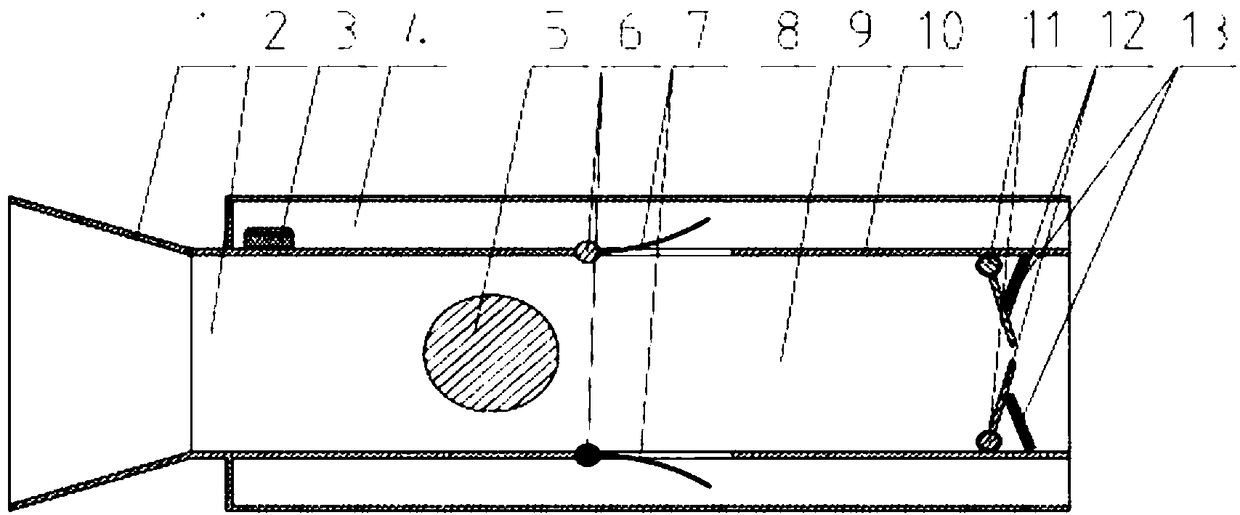
[0064] figure 2 Half-section assembly drawing of the piezoelectric energy harvester, figure 2 (1) is the outer flare, (2) is the front inner chamber, (3) is the circuit module, (4) is the outer chamber, (5) is the fluid around the cylinder, (8) is the piezoelectric component, ( 9) is the rear inner chamber, (10) is a partition plate, (11) is a latch, (12) is a pressure relief door, and (13) is a spring. from figure 2 The main components of t...
Embodiment 2
[0073] The motion of each component is as follows figure 1 shown.
[0074] Figure 4 Half-section assembly drawing of piezoelectric energy harvester, Figure 5 Among them, (5) is the fluid around the cylinder, and (8) is the piezoelectric ceramic beam. from Figure 5 It can be seen that the piezoelectric energy harvester is designed with two cylindrical fluids and four sets of piezoelectric components.
[0075] Figure 5 It is a schematic diagram of the half-section three-dimensional structure of the piezoelectric energy harvester, from which the internal structure of the piezoelectric energy harvester can be seen.
[0076] Image 6 It is a three-dimensional schematic diagram of the inner chamber, from which the installation position and structural form of the piezoelectric ceramic beam can be seen.
[0077] Figure 7 It is a three-dimensional schematic diagram of the piezoelectric energy harvester, the solid line represents the external structure of the piezoelectric ...
Embodiment 3
[0083] The motion of each component is as follows figure 1 shown.
[0084] Figure 8 It is a schematic diagram of the half-section three-dimensional structure of the piezoelectric energy harvester. It can be seen from the figure that two sets of piezoelectric components are added in the middle position of the inner chamber (9).
[0085] Figure 9 Schematic diagram of a piezoelectric energy harvester. The solid line is the external structure of the piezoelectric energy harvester, and the dotted line is the internal structure of the piezoelectric energy harvester. The overall structure and layout of the piezoelectric energy harvester can be seen from the figure.
[0086]Compared with Example 2, the main difference is that the piezoelectric component (8) is installed in the downstream area of the cylinder around the fluid (5), with the downstream centerline of the rear inner chamber (9) as the reference position. The piezoelectric component (8) is composed of a depressed c...
PUM
 Abstract
Description
Claims
Application Information
 - R&D
- Intellectual Property
- Life Sciences
- Materials
- Tech Scout
- Unparalleled Data Quality
- Higher Quality Content
- 60% Fewer Hallucinations
Browse by: Latest US Patents, China's latest patents, Technical Efficacy Thesaurus, Application Domain, Technology Topic, Popular Technical Reports.
© 2025 PatSnap. All rights reserved.Legal|Privacy policy|Modern Slavery Act Transparency Statement|Sitemap|About US| Contact US: help@patsnap.com


