Current calibrating method and device of permanent magnet synchronous motor (PMSM)

A permanent magnet synchronous motor, demagnetizing current technology, applied in the direction of controlling electromechanical transmission, controlling generator, motor generator control, etc., can solve the problems of cumbersome work process and low efficiency, and achieve easy on-site operation and simple operation process. , the effect of small motor runaway risk

Pending Publication Date: 2018-10-23
JING JIN ELECTRIC TECH CO LTD
View PDF5 Cites 27 Cited by
  • Summary
  • Abstract
  • Description
  • Claims
  • Application Information

AI Technical Summary

Problems solved by technology

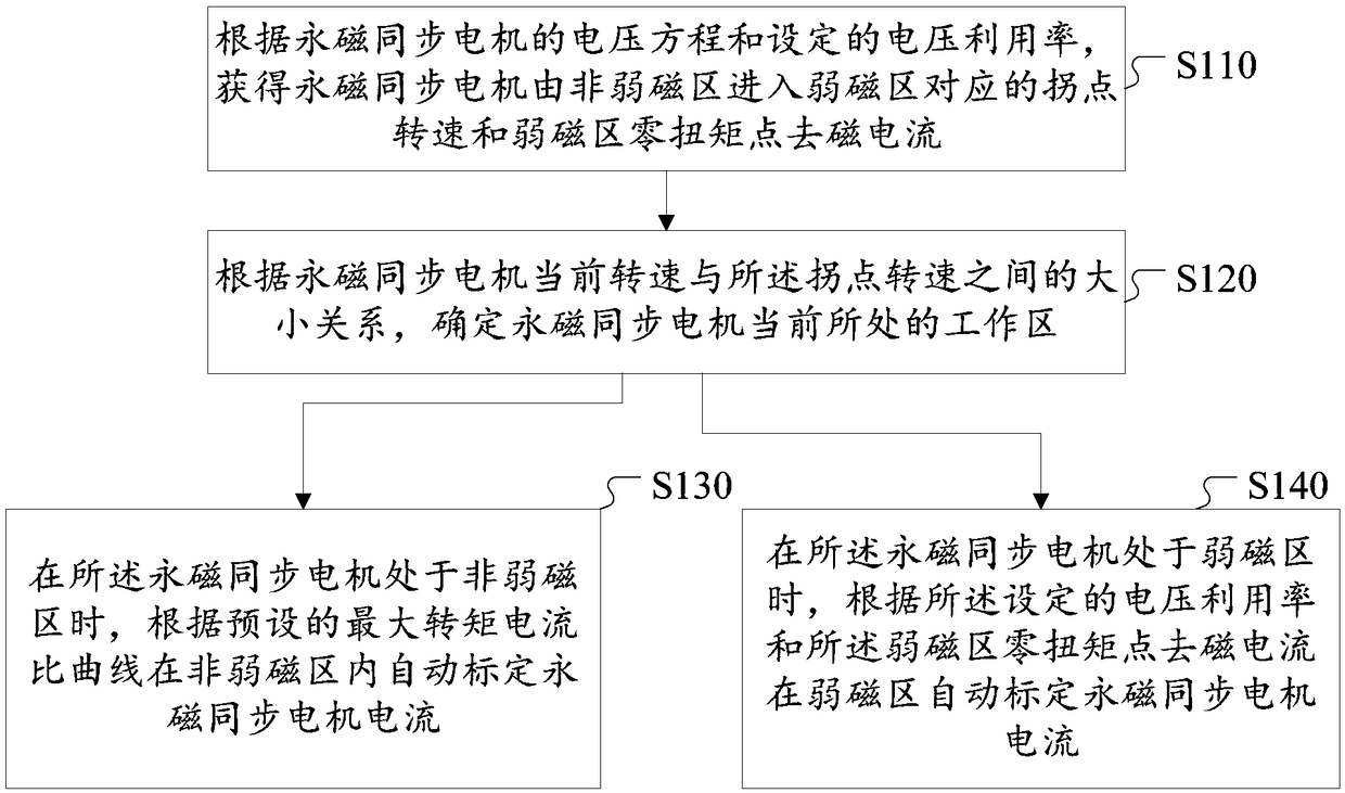
[0004] The present invention provides a method and device for calibrating the current of a permanent magnet synchronous motor to solve the problem of cumbersome work process and low efficiency caused by manually calibrating the current of a permanent magnet synchronous motor in the existing scheme

Method used


Image

  • Current calibrating method and device of permanent magnet synchronous motor (PMSM)
  • Current calibrating method and device of permanent magnet synchronous motor (PMSM)
  • Current calibrating method and device of permanent magnet synchronous motor (PMSM)

Examples


Embodiment Construction

[0029] In order to make the object, technical solution and advantages of the present invention clearer, the implementation manner of the present invention will be further described in detail below in conjunction with the accompanying drawings.

[0030] Hereinafter, embodiments of the present invention will be described with reference to the drawings. It should be understood, however, that these descriptions are exemplary only and are not intended to limit the scope of the present invention. Also, in the following description, descriptions of well-known structures and techniques are omitted to avoid unnecessarily obscuring the concept of the present invention.

[0031] The terminology used herein is for the purpose of describing particular embodiments only, and is not intended to be limiting of the invention. The words "a", "an" and "the" used herein shall also include the meanings of "plurality" and "multiple", unless the context clearly indicates otherwise. In addition, the...


PUM


Abstract

The invention discloses a current calibrating method and device of a PMSM. The method comprises that an inflection-point rotating speed at which the PMSM enters a weak magnetic area form a non-weak magnetic area and a zero-torque-point demagnetizing current in the weak magnetic area are obtained according to a voltage equation and a set voltage utilization rate of the PMSM; a working area where the PMSM is positioned at present is determined according to the relation of the present rotating speed and the inflection-point rotating speed of the PMSM; when the PMSM is positioned in the non-weak magnetic area, the current of the PMSM in the non-weak magnetic area is calibrated automatically according to a preset maximal torque-current ratio curve; and when the PMSM is positioned in the weak magnetic area, the current of the PMSM in the weak magnetic area is calibrated according to the set voltage utilization rate and the zero-torque-point demagnetizing current in the weak magnetic area. Thus, the calibration time can be shortened substantially, the calibration efficiency is improved, and it is ensured that calibration data is consistent and reliable.

Description

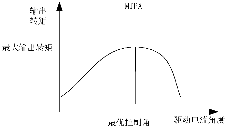
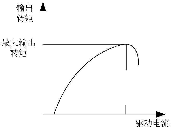
technical field [0001] The invention relates to the technical field of motor control, in particular to a method and device for calibrating the current of a permanent magnet synchronous motor. Background technique [0002] Due to its high power density, high reliability and high efficiency, permanent magnet synchronous motors (Permanent Magnet Synchronous Motor, PMSM) have been widely used in electric vehicles and other demanding speed control drive systems. When controlling the PMSM, a maximum torque-to-current ratio (Maximum Torque Per Ampere, MTPA) algorithm is generally used to optimally match the drive current and torque of the PMSM. In actual operation, the quadrature-axis and direct-axis inductance, quadrature-axis and direct-axis current of PMSM are nonlinearly related to temperature, and this nonlinear relationship is extremely difficult to measure. Therefore, the actual output corresponding to the driving current is generally calibrated The torque performs the opti...

Claims


Application Information

Patent Timeline
Patent Type & Authority Applications(China)
IPC IPC(8): H02P21/00H02P21/22
CPCH02P21/0089H02P21/22
Inventor 郝斌贾景国叶晓
Owner JING JIN ELECTRIC TECH CO LTD
Why Eureka
Try Eureka