Combined multiplexer and signal transmitting method and signal receiving method

A multiplexer and combined technology, which is applied in the direction of connecting devices, waveguide devices, and multiple uses of transmission paths, can solve problems such as difficult implementation

Inactive Publication Date: 2018-10-23
ZTE CORP
View PDF5 Cites 2 Cited by
  • Summary
  • Abstract
  • Description
  • Claims
  • Application Information

AI Technical Summary

Problems solved by technology

[0003] However, for the carrier aggregation frequency band combination of the operator, when the wireless communication device needs to receive and / or signals of at least two frequency bands, if the frequency band interval between the two frequency bands is small, the above-mentioned method of using antenna separation supports multi-band signal transmission and reception plan will be difficult to implement

Method used


Image

  • Combined multiplexer and signal transmitting method and signal receiving method
  • Combined multiplexer and signal transmitting method and signal receiving method
  • Combined multiplexer and signal transmitting method and signal receiving method

Examples


no. 1 example

[0031]The first embodiment of the present invention provides a combined multiplexer, which can be applied to the wireless communication device described above.

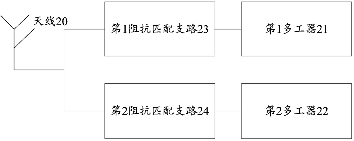
[0032] figure 2 It is a structural schematic diagram of the combined multiplexer of the first embodiment of the present invention, as figure 2 As shown, the wireless communication device is provided with an antenna 20 for sending and receiving radio frequency signals, and the combined multiplexer includes: a first multiplexer 21, a second multiplexer 22, and an antenna located at the first multiplexer 21 The first impedance matching branch 23 between the common input end and the antenna 20, and the second impedance matching branch 24 between the common input end of the second multiplexer 22 and the antenna 20; wherein ,

[0033] The applicable frequency bands of the first multiplexer 21 and the second multiplexer 22 are different from each other, and the first impedance matching branch 23 is used to realize the im...

no. 2 example

[0051] In order to better reflect the purpose of the present invention, further illustrations are made on the basis of the first embodiment of the present invention.

[0052] In the second embodiment of the present invention, the first multiplexer is a quadruplexer, and the second multiplexer is a duplexer, Figure 6 It is a structural schematic diagram of the combined multiplexer of the second embodiment of the present invention, such as Figure 6 As shown, on the one hand, the antenna 20 is connected to the common input end of the first multiplexer 21 through the capacitor C1; An inductor L1 is connected between the multiplexer 21 and the ground, and a capacitor C2 is connected between the second multiplexer and the ground; here, the branch formed by the capacitor C1 and the inductor L1 is the first impedance matching branch, and the capacitor C2 and the inductor L2 are formed The branch is the second impedance matching branch.

[0053] The performance of the combined mult...

no. 3 example

[0060] The third embodiment of the present invention provides a signal sending method, which is based on the combined multiplexer of the first embodiment of the present invention.

[0061] The signaling methods include:

[0062] sending the first radio frequency signal to the antenna through the first multiplexer and the first impedance matching branch in sequence, and using the antenna to send the radio frequency signal from the first impedance matching branch to the outside; and,

[0063] sending the second radio frequency signal to the antenna through the second multiplexer and the second impedance matching branch in sequence, and using the antenna to send the radio frequency signal from the second impedance matching branch to the outside;

[0064] Wherein, the frequency band in which the first radio frequency signal is located is different from the frequency band in which the second radio frequency signal is located.

[0065] Further, in the combined multiplexer, the i-th m...


PUM

PropertyMeasurementUnit
Capacitanceaaaaaaaaaa
Inductance valueaaaaaaaaaa

Abstract

The embodiment of the invention provides a combined multiplexer and a signal transmitting method and signal receiving method. The combined multiplexer is located in a wireless communication device. Anantenna for transmitting and receiving a radio frequency signal is set on the wireless communication device. The combined multiplexer comprises a first multiplexer, a second multiplexer, a first impedance matching branch circuit located between a public input end of the first multiplexer and the antenna, and a second impedance matching branch circuit located between the public input end of the second multiplexer and the antenna. Frequency bands to which the first multiplexer and the second multiplexer are applicable are different. The first impedance matching branch circuit is used for realizing impedance matching of the antenna and the first multiplexer. The second impedance matching branch circuit is used for realizing the impedance matching of the antenna and the second multiplexer.

Description

technical field [0001] The present invention relates to the field of carrier aggregation, in particular to a combined multiplexer and a signal sending and receiving method thereof. Background technique [0002] At present, the spectrum resources of mobile communication are generally relatively tight, and the spectrum resources allocated to each operator may be scattered. For example, the spectrum resources allocated to a certain operator include: B13, B5, B29, B2, B4, B30, etc. For the LTE spectrum resources in the frequency bands, in order to effectively utilize these precious spectrum resources, a carrier aggregation (Carrier Aggregation, CA) method can be adopted, so that wireless communication equipment is required to support transceivers in these frequency bands to work simultaneously. For a radio frequency solution that needs to simultaneously support high, medium, and low frequency band carrier aggregation requirements, it is recommended to use antenna separation in t...

Claims


Application Information

Patent Timeline
IPC IPC(8): H04L5/00
CPCH04L5/003H01P1/20H01P5/16H03H9/46H04B1/38H04L5/00
Inventor 李远勇
Owner ZTE CORP
Why Eureka
Try Eureka