Check patentability & draft patents in minutes with Patsnap Eureka AI!

Ceramic lattice

A technology of ceramics and grids, applied in the field of ceramic grids, which can solve the problems of increased resistance and high thermal conductivity

Active Publication Date: 2018-10-23
MITSUI MINING & SMELTING CO LTD
View PDF11 Cites 6 Cited by
  • Summary
  • Abstract
  • Description
  • Claims
  • Application Information

AI Technical Summary

Problems solved by technology

According to this document, by using aluminum nitride as a ceramic, since the maximum temperature that can be used is higher than that of oxide ceramics represented by alumina and magnesia, and the thermal conductivity is also large, it is considered that the heat of rapid heating and rapid cooling Excited resistance will increase

Method used


Image

  • Ceramic lattice
  • Ceramic lattice
  • Ceramic lattice

Examples


Embodiment 1

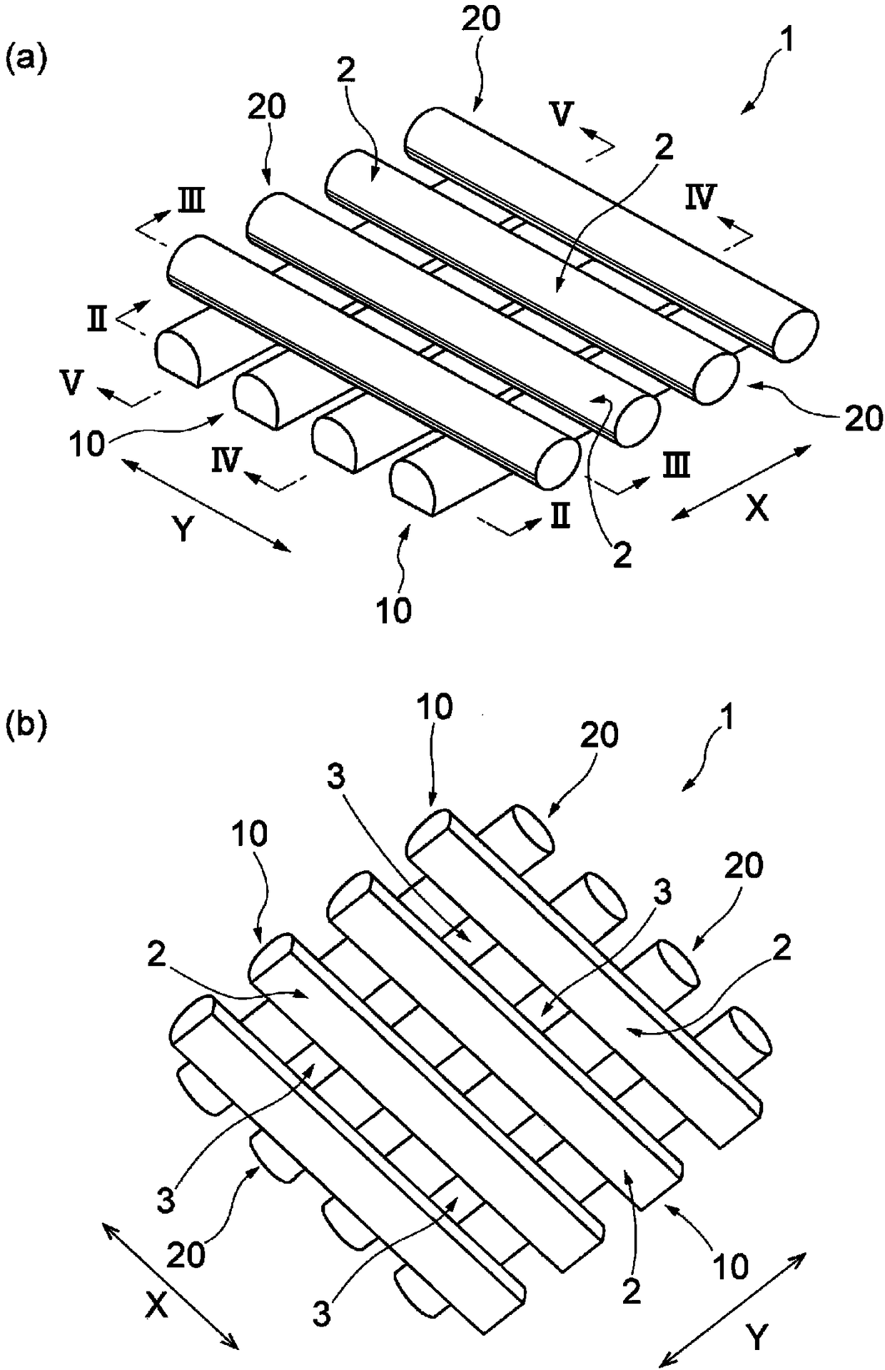
[0096] This example produced Figure 1 to Figure 8 The ceramic grid body 1 shown.

[0097] (1) Preparation of paste for forming line-coated body

[0098] 65.3 parts of 3 mol% yttria-added partially stabilized zirconia powder with an average particle diameter of 0.8 μm, 5.0 parts of hydroxypropyl methylcellulose (average degree of polymerization: 300,000 g / mol) as a water-based binder, as 2.5 parts of glycerin as a plasticizer, 1.1 parts of a polycarboxylic acid-based dispersant (molecular weight: 12,000), and 26.1 parts of water were mixed and defoamed to prepare a paste. The viscosity of the paste was 2.3 MPa·s at 25°C.

[0099] (2) Formation of line coating body

[0100] Using the above-mentioned paste as a raw material, a line first coating body was formed on a resin substrate using a dispenser having a nozzle having a diameter of 0.4 mm. Next, hot air was blown on the first line-coated body using a dryer to remove water, and the first line-coated body was dried. The w...

Embodiment 2

[0104] This example produced Figure 9 ~ Figure 14 Shown is a ceramic grid body 1A.

[0105] (1) Preparation of paste for forming line-coated body

[0106] Add 65.3 parts of fully stabilized zirconia powder to 8 mol% yttrium oxide with an average particle diameter of 0.8 μm, and 5.0 parts of hydroxypropyl methylcellulose (average degree of polymerization: 300,000 g / mol) as a water-based binder, as 2.5 parts of glycerin as a plasticizer, 1.1 parts of a polycarboxylic acid-based dispersant (molecular weight: 12,000), and 26.1 parts of water were mixed and defoamed to prepare a paste. The viscosity of the paste was 2.3 MPa·s at 25°C.

[0107] (2) Formation of line coating body

[0108] Using the above-mentioned paste as a raw material, a line first coating body was formed on a resin substrate using a dispenser having a nozzle having a diameter of 0.4 mm, and then a line second coating body crossing it was formed. The intersection angle of the two-line coating body was set to ...

Embodiment 3

[0112] A ceramic grid body was obtained in the same manner as in Example 2 except that the diameter of the nozzle was set to 0.8 mm. As far as the obtained grid body is concerned, if Figure 14 As shown in , the corners of the rectangular through-holes are rounded.


PUM

PropertyMeasurementUnit
The average particle sizeaaaaaaaaaa
Viscosityaaaaaaaaaa
Viscosityaaaaaaaaaa

Abstract

The present invention provides a ceramic lattice that is of high-strength and superior in spalling resistance. This ceramic lattice (1) has a plurality of first striated parts (10) and a plurality ofsecond striated parts (20). Each of the first striated parts (10) has a cross-sectional shape that, at a place other than an intersection (2), comprises a linear section (10A) and a convex curved section (10B) having two ends thereof formed at both ends of the linear section (10A). Each of the second striated parts (20) has a cross-section that, at a place other than the intersection (2), is of acircular or elliptical shape. In a longitudinal sectional view of the intersection (2), the first striated part (10) and the second striated part (20) are in contact with each other only at the crownof the convex curved section (10B) in the first striated part (10) and the crown of the downward convex section in the circular or elliptical shape of the second striated part (20).

Description

technical field [0001] The present invention relates to a grid body made of ceramics. Background technique [0002] When firing electronic components made of ceramics or glass, the firing is generally carried out by placing an object to be fired on a setter, which is also called a shelf, a backing plate, or the like. In order to shorten the degreasing and firing time of the products to be fired and increase the number of manufactured pieces per unit time, it is necessary to perform rapid heating and rapid cooling in the firing process. However, the existing ceramic setters should be rapidly heated And / or defects such as cracks are prone to occur during quenching. Moreover, defects such as cracks are also prone to occur due to repeated use. Moreover, when metal setters were used, the problem that it cannot be used in an oxidizing atmosphere, and the problem that it deform|transforms greatly when it is used repeatedly in the high temperature range of 1200 degreeC or more was...

Claims


Application Information

Patent Timeline
IPC IPC(8): C04B35/64F27D3/12
CPCC04B35/64F27D3/12C04B41/5042C04B41/87F27D5/0012F27D5/0031
Inventor 黑村哲宗有马峻本田光司
Owner MITSUI MINING & SMELTING CO LTD
Features
  • R&D
  • Intellectual Property
  • Life Sciences
  • Materials
  • Tech Scout
  • Unparalleled Data Quality
  • Higher Quality Content
  • 60% Fewer Hallucinations
Learn More