Control system and method for a line-commutated converter for a high voltage direct current system

A control system and control method technology, applied in the direction of power transmission AC network, etc., can solve problems such as pole commutation failure, achieve the effect of reducing the probability of commutation failure, improving reliability and stability

Active Publication Date: 2022-03-01
HITACHI ENERGY SWITZERLAND AG
View PDF5 Cites 0 Cited by
  • Summary
  • Abstract
  • Description
  • Claims
  • Application Information

AI Technical Summary

Problems solved by technology

This phenomenon can cause the commutation failure of an already operating pole when the other pole is restarted after clearing the DC transmission line fault

Method used


Image

  • Control system and method for a line-commutated converter for a high voltage direct current system
  • Control system and method for a line-commutated converter for a high voltage direct current system
  • Control system and method for a line-commutated converter for a high voltage direct current system

Examples


Embodiment Construction

[0025] In the following description, for purposes of explanation and not limitation, specific details are set forth, such as particular circuits, circuit components, interfaces, techniques, etc., in order to provide a thorough understanding of the present invention. It will be apparent, however, to one skilled in the art that the present invention may be practiced in other embodiments that depart from these specific details. In other instances, detailed descriptions of well-known methods and procedures, devices, and circuits are omitted so as not to obscure the description of the present invention with unnecessary detail.

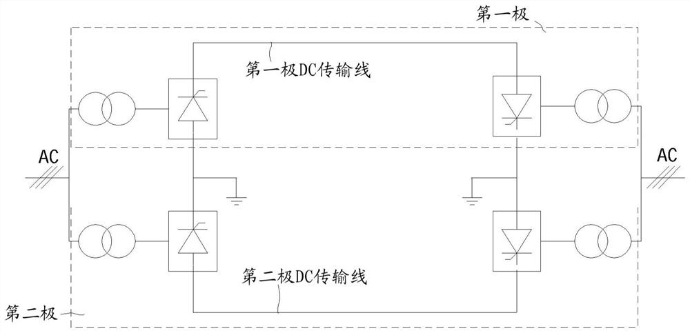
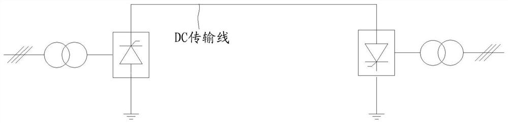
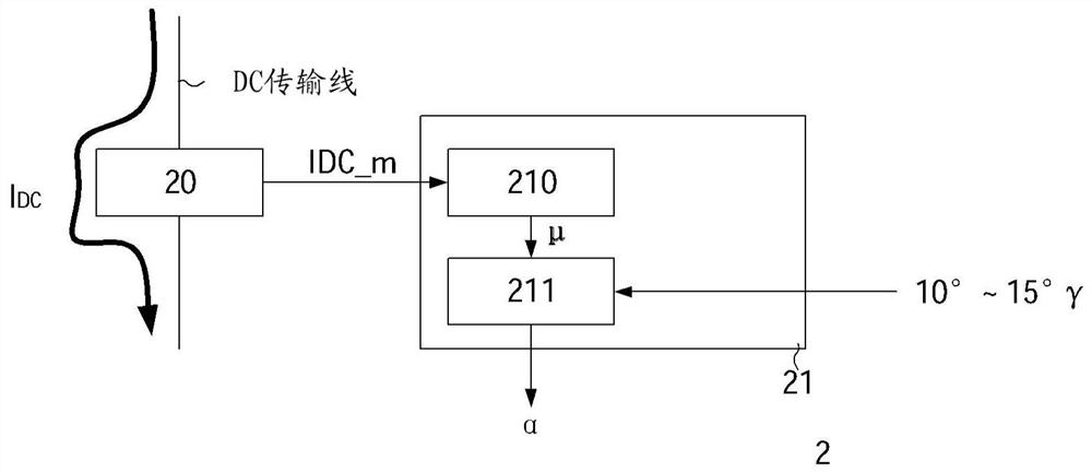
[0026] Figure 2A and Figure 2B A block diagram of a control system for operation of an LCC and a control system of an HVDC system according to an embodiment of the present invention are shown, respectively. Figure 2C The phase commutation process of the LCC according to the embodiment of the present invention is shown.

[0027] as in Figure 2A As sh...


PUM


Abstract

The present invention provides a control system and a control method for the LCC of the HVDC system. The control system includes: a first measurement unit (20) configured to provide a current amount measurement indicative of the DC current flow of the HVDC system; and a controller (21) configured to respond to When the measured value of the current amount exceeds the current reference level, the first arc extinguishing angle during the operation of the controlled LCC is increased to the second arc extinguishing angle, so as to avoid the commutation failure of the controlled LCC. By using the solution of the HVDC system, as the quenching angle of the LCC increases, the probability of commutation failure caused by the rapid rise of the DC current of the HVDC system can be reduced. The reliability and stability of the entire AC and DC power system are improved.

Description

technical field [0001] The present invention relates to the control of line-commutated converters (LCCs) for high voltage direct current (HVDC) systems, and more particularly to preventing commutation failures of LCCs of HVDC systems. Background technique [0002] HVDC systems are typically used to connect a high voltage AC grid or a remote power station to the AC grid. Such systems usually consist of two converter stations interconnected by DC transmission lines or cables. On the generating or transmitting end, the converter includes rectifiers that convert AC power to DC current and voltage, while on the receiving end, converters include inverters that transfer power from the DC transmission line to the AC grid. [0003] A typical HVDC system may include unipolar transmission lines or bipolar transmission lines. Figure 1A and Figure 1B A block diagram of a bipolar HVDC system and a unipolar HVDC system is shown. as in Figure 1A In a bipolar HVDC system, if there is a...

Claims


Application Information

Patent Timeline
Patent Type & Authority Patents(China)
IPC IPC(8): H02J3/36
CPCH02J3/36Y02E60/60
Inventor 马茨·安德森蔡蓉谢海莲张利东
Owner HITACHI ENERGY SWITZERLAND AG
Why Eureka
Try Eureka