Device for cleaning head cover of battery and method of cleaning head cover of battery

A battery and top cover technology, which is applied in the field of cleaning the battery top cover and cleaning the battery top cover, can solve the problems of increasing production costs, unfavorable long-term development of enterprises, and low cleaning efficiency, so as to avoid battery damage, reduce scrap rate, The effect of improving efficiency

Pending Publication Date: 2018-10-26
JIANGSU ZENIO NEW ENERGY BATTERY TECH CO LTD
View PDF7 Cites 0 Cited by
  • Summary
  • Abstract
  • Description
  • Claims
  • Application Information

AI Technical Summary

Problems solved by technology

The above-mentioned scheme can remove large particles of dirt to a certain extent, but this scheme still has the following defects at least: First, it cannot remove the colloidal particles and electrostatically charged particles attached to the edge of the top cover, which will cause welding explosion points during welding , affecting the quality of the battery. Second, the cleaning device is large in size and low in cleaning efficiency. Third, the energy consumption in the production process is large, which increases production costs and is not conducive to the long-term development of the enterprise.

Method used


Image

  • Device for cleaning head cover of battery and method of cleaning head cover of battery
  • Device for cleaning head cover of battery and method of cleaning head cover of battery

Examples


Embodiment 1

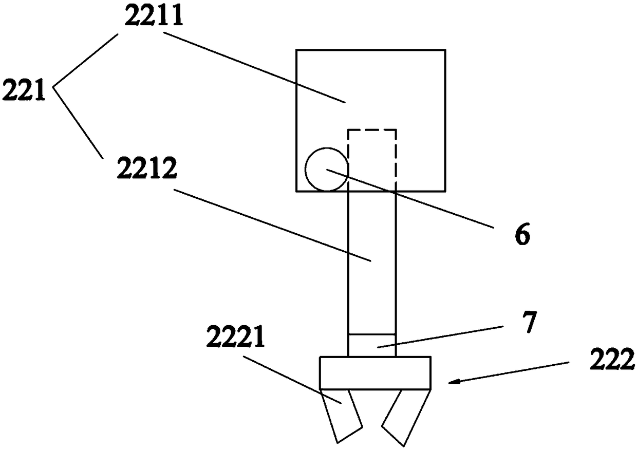
[0027] Such as Figure 1~2 As shown, a device for cleaning the battery top cover includes a delivery mechanism 1 for transporting batteries and a laser cleaning mechanism 2 for cleaning the battery top cover on the delivery mechanism 1. The laser cleaning mechanism 2 includes a cleaning box 21, and The grabbing device 22 connected to the cleaning box 21 and the positioning device 23 arranged in the cleaning box 21, the cleaning box 21 includes a front plate 211, a rear plate 212, two side plates 213 and a top plate 214, a front plate 211, a rear plate 212 1. The two side plates 213 and the top plate 214 form a frame structure, the top plate 214 is provided with a laser vibrating mirror 5 , the grabbing device 22 is fixed on the top plate 214 , and the positioning device 23 is fixed on the side plate 213 . Set up the grabbing device 22 to avoid damage to the battery caused by manual grabbing, and at the same time improve the efficiency of grabbing the battery, thereby increasin...

Embodiment 2

[0032] Such as Figure 1~2 As shown, a method of using the device of embodiment 1 to clean the top cover of the battery comprises the following steps:

[0033] 1) Transport the battery to the cleaning box 21 through the conveyor belt 12, and the main control device 215 controls the mechanical gripper 222 to grab the battery into the cleaning box 21;

[0034] 2) The main control device 215 controls the mechanical gripper 222 to rotate the battery, while the positioning device 23 photographs and positions the top cover and the edge of the aluminum case of the battery, and feeds back to the main control device 215 in real time.

[0035] 3) The main control device 215 controls the laser vibrating mirror 5 to clean the top cover and the edge of the aluminum case of the battery according to the feedback information. After the cleaning is completed, the grabbing device 22 puts the battery back into the conveying mechanism 1 for the next process.

[0036] It should also be explained ...


PUM


Abstract

The invention belongs to the technical field of cleaning devices, and in particular relates to a device for cleaning a head cover of a battery. The device comprises a conveying mechanism (1) and a laser cleaning mechanism (2) for cleaning the head cover of the battery on the conveying mechanism (1), wherein the laser cleaning mechanism (2) comprises a cleaning box (21), a grabbing device (22) connected to the cleaning box (21) and a positioning device (23) arranged in the cleaning box (21). The device provided by the invention can be used for removing colloidal particles and electrostatic particles attached to the edge of the head cover, and meanwhile can prevent the battery from being damaged. The device is relatively small in size, high in cleaning speed and pollution-free. The energy consumption in the production process can be also reduced, the production cost is lowered, and long-term development of an enterprise is facilitated. In addition, the invention also discloses a method of cleaning the head cover of the battery.

Description

technical field [0001] The invention belongs to the technical field of cleaning devices, and in particular relates to a device for cleaning a battery top cover and a method for cleaning the battery top cover. Background technique [0002] As a new type of secondary battery, lithium-ion batteries have the advantages of high energy density and power density, high working voltage, light weight, small size, long cycle life, good safety, and environmental protection. They are widely used in portable appliances, electric tools, large Energy storage, electric transportation power supply and other aspects have broad application prospects. There will be some corrosive and dirty residue on the top cover of the battery. Cleaning in time is an effective way to ensure that the surface of the battery is clean and rust-free. The traditional manual cleaning method is inefficient and it is difficult to clean thoroughly. In the conveyor belt cleaning machines that are common in the market t...

Claims


Application Information

Patent Timeline
Patent Type & Authority Applications(China)
IPC IPC(8): B08B7/00B08B13/00
CPCB08B7/0042B08B13/00
Inventor 覃涛王亚汤守巧韩玮
Owner JIANGSU ZENIO NEW ENERGY BATTERY TECH CO LTD
Why Eureka
Try Eureka