Novel micro-motion boring cutter structure

A boring tool and a new type of technology, applied in the accessories of tool holders, tools for lathes, turning equipment, etc., can solve the problems of complex design, complex manufacturing, and many processing procedures, and achieve increased processing range and tool head manufacturing. The effect of simplicity and miniaturization of parts

Active Publication Date: 2018-10-26
GUIZHOU AEROSPACE PRECISION PRODS
View PDF10 Cites 1 Cited by
  • Summary
  • Abstract
  • Description
  • Claims
  • Application Information

AI Technical Summary

Problems solved by technology

[0002] In mechanical boring processing, there are many types of boring tools, but the design is more complicated
like image 3 The traditional internal and external boring tool holders shown are relatively complicated to manufacture and have many processing procedures; and the processing range of each tool holder is small

Method used


Image

  • Novel micro-motion boring cutter structure
  • Novel micro-motion boring cutter structure
  • Novel micro-motion boring cutter structure

Examples


Embodiment Construction

[0022] The present invention will be described in further detail below in conjunction with the accompanying drawings.

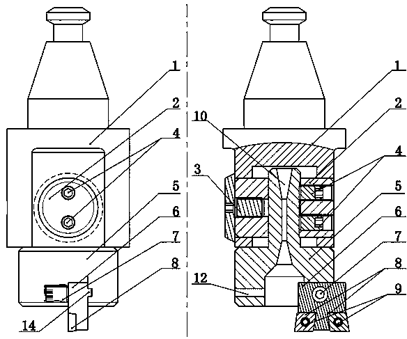
[0023] Such as figure 1 , figure 2 , Figure 4 , Figure 5 A new type of micro-motion boring tool structure of the present invention is shown, including a main body 1, a sliding device 2 installed on one side of the main body 1, a micro-motion adjustment device 3 installed on the other side of the main body 1, a tool bar 5, and a cutter head 6 , the blade 8; the cutter bar 5 and the cutter head 6 are split structures; the inside of the cutter bar 5 is provided with a water outlet 10 that runs through the cutter bar 5, and the upper part of the cutter bar 5 is installed in the main body 1 and passed through the locking screw 4 Connected to the sliding device 2, the lower part of the cutter bar 5 is in the shape of a cylinder, and a rectangular notch 11 is provided at the bottom of the cutter bar 5; one side of the rectangular notch 11 is provided with a c...


PUM


Abstract

The invention provides a novel micro-motion boring cutter structure. The novel micro-motion boring cutter structure comprises a main body, a sliding device, a micro-motion adjusting device, a cutter bar, a cutter bit and blades; the cutter bar and the cutter bit are separate; a water outlet which penetrates through the cutter bar vertically is formed in the cutter bar, the upper portion of the cutter bar is mounted in the main body, and is connected to the sliding device through locking screws, and a rectangular notch is further formed in the bottom of the cutter bar; a cutter bar positioninggroove is formed in one side of the rectangular notch, and a cutter bit locking screw hole is formed in the other side of the rectangular notch; the upper portion of the cutter bit is clamped in the rectangular notch, and can be fastened in the rectangular notch through a cutter bit locking screw; a cutter bit positioning projection which is exactly clamped in the cutter bar positioning groove isarranged on a side surface of the upper portion of the cutter bit; and the blades are mounted on the bottom of the cutter bit through pressing screws. The boring cutter structure is simple to manufacture; because the cutter bar is divided into two portions, the production cost is reduced effectively; and the cutter bit can slide in the rectangular notch along the cutter bar positioning groove, therefore, the machinable range of the single cutter bit is large, and cutter orientation and size adjustable are facilitated.

Description

technical field [0001] The invention relates to the field of mechanical cutting, in particular to a novel micro-motion boring tool structure mainly used for machining high-precision inner and outer circles. Background technique [0002] In mechanical boring processing, there are many types of boring tools, but the design is more complicated. Such as image 3 The traditional inner and outer boring tool holders shown are relatively complicated to manufacture, and there are many processing steps; and each tool holder can process a small range. Contents of the invention [0003] In view of the above problems, the object of the present invention is to provide a new type of micro-motion boring tool structure that can perform high-precision inner circle machining and high-precision outer circle machining. [0004] A new type of micro-motion boring tool structure, including a main body, a sliding device installed on one side of the main body, a micro-motion adjustment device inst...

Claims


Application Information

Patent Timeline
IPC IPC(8): B23B27/10B23B27/16
CPCB23B27/10B23B27/1662B23B27/1685
Inventor 陈长青唐代涛
Owner GUIZHOU AEROSPACE PRECISION PRODS
Why Eureka
Try Eureka