Curvilinear and straight chip removal combined grinding wheel

A combination of grinding wheel technology, applied in the field of grinding wheels, can solve problems such as accelerated grinding wheel wear, poor chip removal, and heat dissipation effects, and achieve the effects of enhancing heat dissipation, increasing chip removal channels, and facilitating safe production

Inactive Publication Date: 2018-10-26
刘雪松
View PDF2 Cites 1 Cited by
  • Summary
  • Abstract
  • Description
  • Claims
  • Application Information

AI Technical Summary

Problems solved by technology

In engineering use, when the grinding wheel is grinding or cutting materials, the grinding contact area between the grinding wheel and the workpiece is large, and the grinding heat is difficult to discharge in time, thus forming a local high temperature on the grinding surface, causing problems such as burns and cracks on the surface of the workpiece, which are serious It affects the surface processing quality of the workpiece, and accelerates the wear of the grinding wheel, which restricts the further popularization and application of grinding technology
In addition, after the grinding wheel has been used for a period of time, if a local wear defect occurs, the entire grinding wheel needs to be replaced, resulting in serious waste
[0003] Application number 201521112770.1 discloses a grinding wheel with chip removal grooves, which has multiple chip removal grooves radially on the side where the abrasive layer is in contact with the workpiece, but its chip removal capacity is not ideal enough, and the bottom of the chip removal grooves For rectangular corners, it is easy to cause accumulation of wear debris and affect the effect of chip removal
Application No. 201020166002.5 discloses a grinding wheel that is easy to dissipate heat. The adopted technical solution is to connect the aluminum core through the hole in the center of the grinding wheel disc body and design annular grooves on the upper and lower surfaces of the disc body for heat dissipation, but the heat dissipation effect is not very satisfactory. There is no relationship between the grooves, which will affect the heat dissipation effect, and it will easily cause abrasive debris filling and poor chip removal, scratching the surface of the workpiece

Method used


Image

  • Curvilinear and straight chip removal combined grinding wheel
  • Curvilinear and straight chip removal combined grinding wheel
  • Curvilinear and straight chip removal combined grinding wheel

Examples


Embodiment Construction

[0032] The technical solutions of the various embodiments of the present invention will be clearly and completely described below in conjunction with the accompanying drawings. Apparently, the described embodiments are only some of the embodiments of the present invention, not all of them. Based on the embodiments of the present invention, all other embodiments obtained by persons of ordinary skill in the art without making creative efforts fall within the protection scope of the present invention.

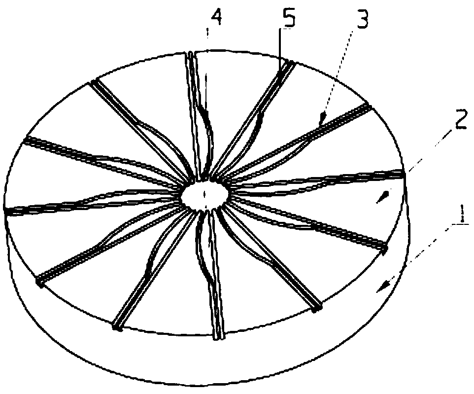
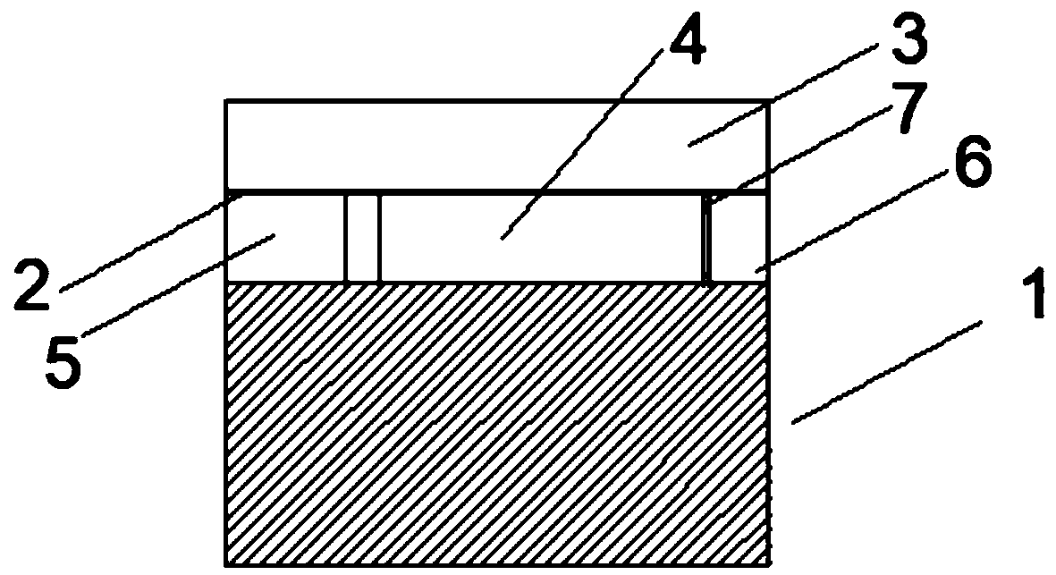
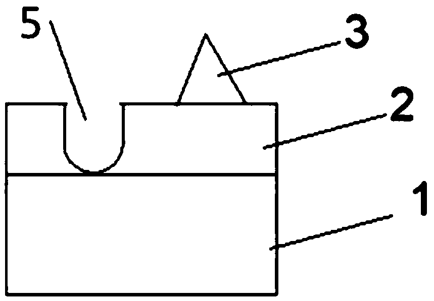
[0033] Such as figure 1 , figure 2 As shown, a grinding wheel combining curved chip removal and straight chip removal is provided, including a grinding wheel base 1, a mounting shaft hole 6 is opened at the center of the grinding wheel base 1, and a The abrasive layer 2 is provided with a relief installation hole 7 corresponding to the installation shaft hole 6 at the central position of the abrasive layer 2, and 12 convex ribs 3 are arranged radially on the end surface of the a...


PUM


Abstract

A curvilinear and straight chip removal combined grinding wheel comprises a grinding wheel base body, wherein a mounting shaft hole is formed in the center of the grinding wheel base body; an abrasivelayer is arranged on one side of the grinding wheel base body; a yielding mounting hole that corresponds to the mounting shaft hole is formed in the center of the abrasive layer; a plurality of flanges are formed on the end surface, in contact with a workpiece, of the abrasive layer in a radial direction and uniformly distributed on the end surface; arc-shaped grooves that extend in the radial direction are formed between the flanges and formed in the abrasive layer; a chip removal runner of each arc-shaped groove is formed by combining a curvilinear chip removal runner and a straight chip removal runner; a lug boss is formed on each flange; and sunken grooves that are embedded into the lug bosses are formed in the end surface, in contact with the workpiece, of the abrasive layer. By means of the flanges and the arc-shaped grooves, the chip removal capability and the heat dissipation capability of the grinding wheel can be effectively improved, the grinding accuracy of the grinding wheel is improved, and the service life of the grinding wheel is prolonged.

Description

technical field [0001] The invention relates to the technical field of grinding wheels, in particular to a grinding wheel combining curved chip removal and straight chip removal. Background technique [0002] At present, the commonly used shapes of grinding wheels include parallel grinding wheel, single concave grinding wheel, double-sided concave grinding wheel, thin slice grinding wheel, cylindrical grinding wheel, bowl-shaped grinding wheel, butterfly grinding wheel and so on. In engineering use, when the grinding wheel is grinding or cutting materials, the grinding contact area between the grinding wheel and the workpiece is large, and the grinding heat is difficult to discharge in time, thus forming a local high temperature on the grinding surface, causing problems such as burns and cracks on the surface of the workpiece, which are serious It affects the surface processing quality of the workpiece, and accelerates the wear of the grinding wheel, which restricts the furt...

Claims


Application Information

Patent Timeline
Patent Type & Authority Applications(China)
IPC IPC(8): B24D7/06
CPCB24D7/06
Inventor 刘雪松
Owner 刘雪松
Why Eureka
Try Eureka