Reinforced fuel tank and method for reinforced fuel tank construction

A technology of fuel tanks and plastic materials, applied in the direction of layout, application, substructure, etc. combined with the fuel supply of internal combustion engines, which can solve the problems of long cycle time, not easy to obtain, high machining cost, etc.

Active Publication Date: 2018-10-26
FORD GLOBAL TECH LLC
View PDF8 Cites 2 Cited by
  • Summary
  • Abstract
  • Description
  • Claims
  • Application Information

AI Technical Summary

Problems solved by technology

The split blank molding process has several drawbacks such as longer cycle times than other fuel tank construction techniques, higher machining costs, and the split blank molding process requires specialized machinery not readily available in many manufacturing facilities

Method used


Image

  • Reinforced fuel tank and method for reinforced fuel tank construction
  • Reinforced fuel tank and method for reinforced fuel tank construction
  • Reinforced fuel tank and method for reinforced fuel tank construction

Examples


Embodiment Construction

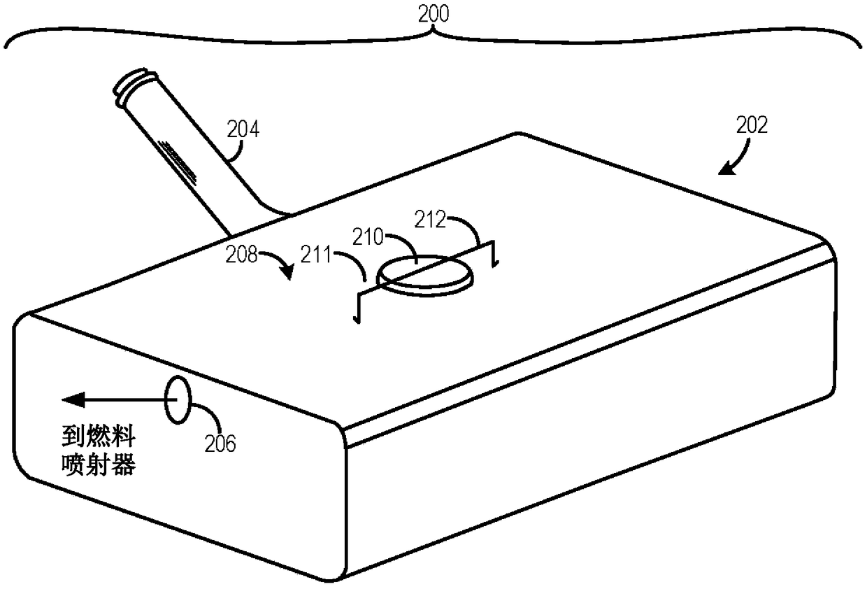
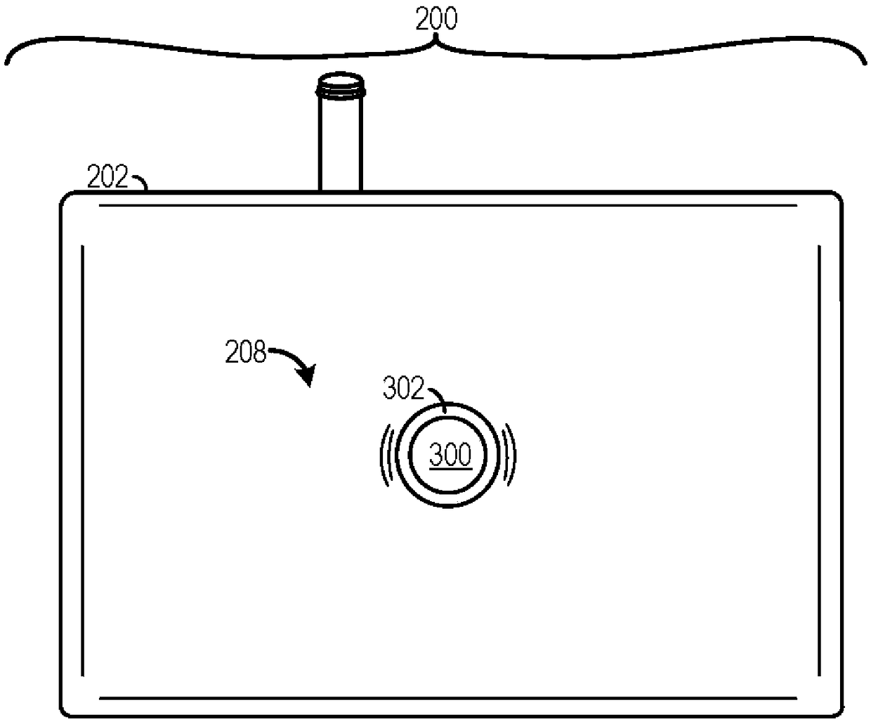
[0014] A method for constructing a fuel tank having struts that provide fuel tank reinforcement is described herein. The fuel tank construction method includes several steps that enable to reduce the production costs of the fuel tank while increasing the strength of the fuel tank shell. The method includes snap fitting the strut with a flange surrounding an opening in the fuel tank housing. The method may also include welding the ends of the struts to the walls of the fuel tank. The other end of the strut may be welded to the casing or covered by a cap to seal the fuel tank opening. The snap fit and welding process enables the strut to be efficiently inserted and secured in the desired position in the casing during fuel tank manufacture. In addition, the snap fit and welding process may also enable the fuel tank shell to be manufactured using efficient techniques other than the split half molding technique, such as blow molding. Therefore, the cost of the fuel tank can be k...


PUM


Abstract

A method for manufacturing a fuel tank is described herein. The method includes subsequent to molding of a housing of a fuel tank, positioning a strut inside the housing. The method additionally includes snap-fitting a flexible projection of the strut with a corresponding flange section in a first wall of the housing, the flange section surrounding an opening in the first wall of the housing and the flexible projection including a surface overlapping an interior surface of the flange section subsequent to the snap-fitting.

Description

Background technique [0001] Vehicle fuel tanks may experience large internal pressure changes due to changes in operating conditions within the vehicle and external environmental conditions. Pressure swing may be particularly prevalent in hybrid vehicles due to periods of engine shutdown in hybrid vehicles when compared to vehicles that use only the internal combustion engine for propulsion. Attempts have been made to manufacture fuel tanks by reinforcing columns to reduce the likelihood of elevated negative or positive pressures having detrimental effects on the tank shell (eg, tank deformation, rupture, etc.). However, fuel tanks with reinforced columns have historically required complex manufacturing techniques that can be costly and lengthy. For example, a split semi-finished molding process has been used to construct fuel tanks with columns. The split blank molding process has several drawbacks such as longer cycle times than other fuel tank construction techniques, hig...

Claims


Application Information

Patent Timeline
Patent Type & Authority Applications(China)
IPC IPC(8): B60K15/03
CPCB60K15/03B60K2015/03032B29L2031/7172B60K15/03177B29C2049/2013B60K2015/0346B60K2015/03046B60K2015/03467B29C51/267B60K15/03006B29C49/20B29C2049/206B60K2015/0592B60K2015/03335B60K2015/03059
Inventor B·T·艾特肯M·D·邦格
Owner FORD GLOBAL TECH LLC
Why Eureka
Try Eureka