Stacking frame for concrete prefabricated slab type component

A technology of prefabricated slabs and concrete, which is applied in the direction of external frames, load-hanging components, types of packaging items, etc., can solve the problems of limited stacking quantity and inability to make full use of the vertical space of the stacking yard, and achieve floor space saving, Realize batch hoisting and reduce the area occupied by the construction site

Pending Publication Date: 2018-10-26
锦萧建筑科技有限公司
View PDF0 Cites 5 Cited by
  • Summary
  • Abstract
  • Description
  • Claims
  • Application Information

AI Technical Summary

Problems solved by technology

[0003] The finished concrete precast slabs need to be stored in the component factory for a certain period of time. In order to reduce the land area occupied by the concrete precast slabs, they are generally stacked in a stacked manner. It is generally stipulated that no more than six prefabricated panels should be stacked at the same time. There is a problem that the number of stacked stacks is limited, and the longitudinal space of the yard cannot be fully utilized; therefore, a new solution needs to be proposed to solve this problem

Method used


Image

  • Stacking frame for concrete prefabricated slab type component
  • Stacking frame for concrete prefabricated slab type component
  • Stacking frame for concrete prefabricated slab type component

Examples


Embodiment Construction

[0029] The present invention will be described in further detail below in conjunction with the accompanying drawings.

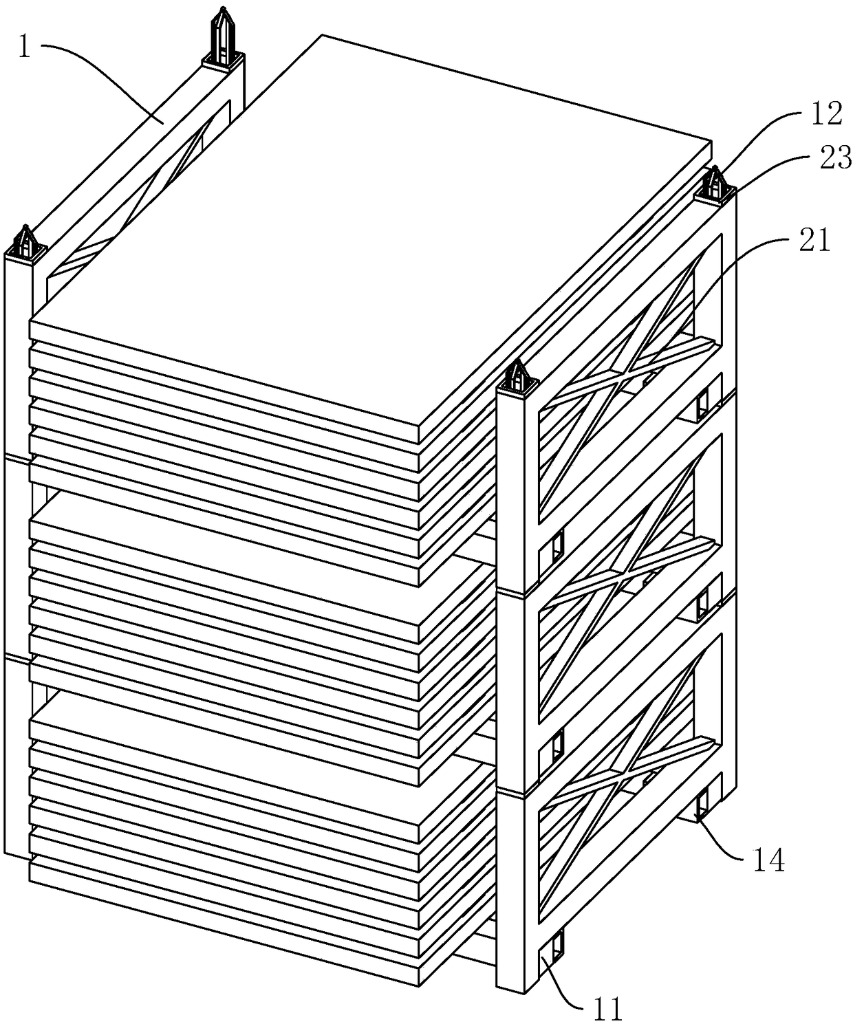
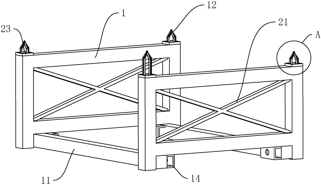
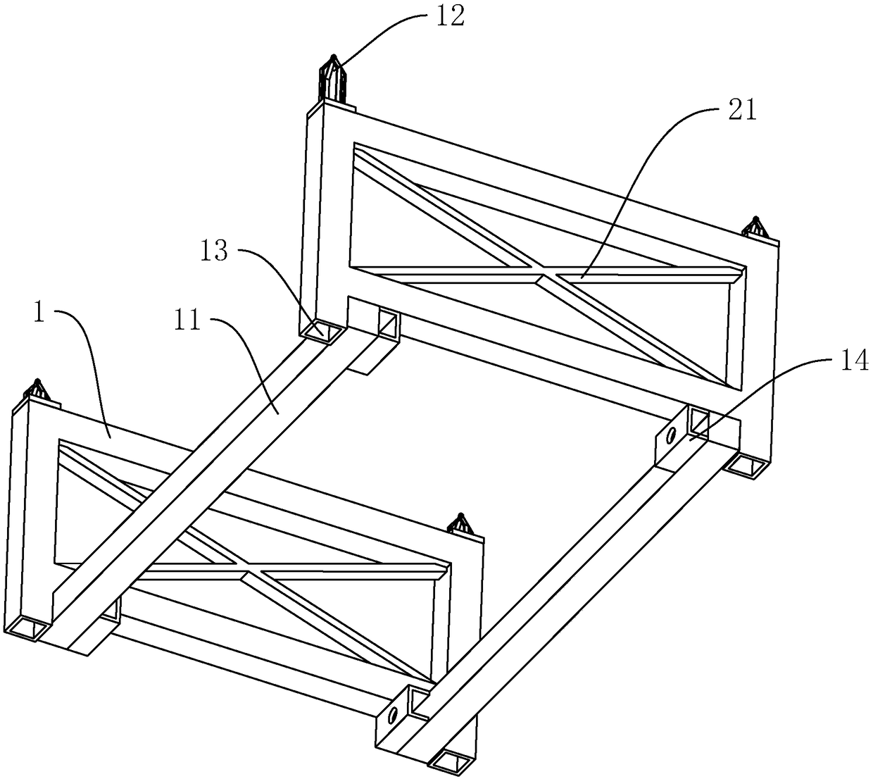
[0030] Stacking racks for concrete prefabricated slabs, such as figure 1 , figure 2 , image 3 As shown, it includes two oppositely arranged rectangular frames 1, and bottom beams 11 welded to both ends of the rectangular frame 1 at the same time. , so that two rectangular frames 1 cooperate with two bottom beams 11 to form a U-shaped placement structure in front view; the two sides of the top of the rectangular frame 1 are respectively provided with socket parts 12, and the two sides of the bottom of the rectangular frame 1 are respectively reserved for The insertion hole 13 into which the insertion part 12 is inserted.

[0031] When it is necessary to stack and stack concrete precast slabs, stack six concrete precast slabs in each stacking rack, lift two stacking racks in turn to align each socket 12 with the corresponding socket hole 13, and will be ho...


PUM


Abstract

The invention discloses a stacking frame for a concrete prefabricated slab type component and relates to a concrete component. The stacking frame for the concrete prefabricated slab type component aims at solving the problems that the superimposed and stacked number of concrete prefabricated slabs is limited, and a longitudinal space of a storage yard can not be made full use of. The technical scheme is that the stacking frame for the concrete prefabricated slab type component comprises two rectangular frames and bottom beams; the rectangular frames are arranged oppositely; the two ends of each bottom beam and the rectangular frames are welded and fixed simultaneously; the number of the bottom beams is two; the two bottom beams are correspondingly fixed to the two sides of the bottom end of each rectangular frame; inserting parts are correspondingly arranged on the two sides of the top end of each rectangular frame; and inserting holes where the inserting parts are inserted are correspondingly formed in the two sides of the bottom end of each rectangular frame. With the adoption of the stacking frame for the concrete prefabricated slab type component, the superimposed and stacked number of the concrete prefabricated slabs is free from being limited, and the technical effects that the longitudinal space is made full use of and a floor area is saved are achieved.

Description

technical field [0001] The invention relates to concrete components, more specifically, it relates to a stacking rack for concrete prefabricated slab components. Background technique [0002] In modern engineering construction, in order to reduce the length of on-site construction, concrete prefabricated parts are increasingly used. Such prefabricated concrete parts are generally produced in the concrete prefabricated component factory, and then transported to the construction site for construction. [0003] The finished concrete precast slabs need to be stored in the component factory for a certain period of time. In order to reduce the land area occupied by the concrete precast slabs, they are generally stacked in a stacked manner. It is generally stipulated that no more than six prefabricated panels should be stacked at the same time. There is a problem that the number of stacked stacks is limited, and the longitudinal space of the yard cannot be fully utilized; therefore...

Claims


Application Information

Patent Timeline
IPC IPC(8): B65D61/00B65D85/62B65D85/46B65D81/02B66C1/12B66C1/66
CPCB65D61/00B65D81/02B65D85/46B65D85/62B66C1/12B66C1/66
Inventor 陆春梁陈象
Owner 锦萧建筑科技有限公司
Why Eureka
Try Eureka