A hydraulic control system for a crane

A hydraulic control system and hydraulic technology, applied in the field of control, can solve problems such as boom shaking, braking too slow by the braking mechanism, too fast or too slow braking of the braking mechanism, etc., to achieve the effect of ensuring work efficiency

Active Publication Date: 2020-03-31
WUHAN MARINE MACHINERY PLANT
View PDF4 Cites 0 Cited by
  • Summary
  • Abstract
  • Description
  • Claims
  • Application Information

AI Technical Summary

Problems solved by technology

[0003] When the luffing winch releases the cable to make the boom of the crane increase and descend, if the release of the cable is stopped suddenly, the boom of the crane will still drop slightly for a certain distance under the action of inertia, and the existing hydraulic control system of the crane cannot Better control the braking time of the luffing winch, so the brake mechanism of the hydraulic control system will brake too fast or too slow when the boom of the crane is lowered due to inertia, and the brake mechanism will brake too fast and cause The boom of the crane shakes a lot, and the brake mechanism brakes too slowly, there may be unexpected situations that cause the position of the boom of the crane to change, both of which will affect the working efficiency of the boom of the crane

Method used


Image

  • A hydraulic control system for a crane

Examples


Embodiment Construction

[0020] In order to make the object, technical solution and advantages of the present invention clearer, the implementation manner of the present invention will be further described in detail below in conjunction with the accompanying drawings.

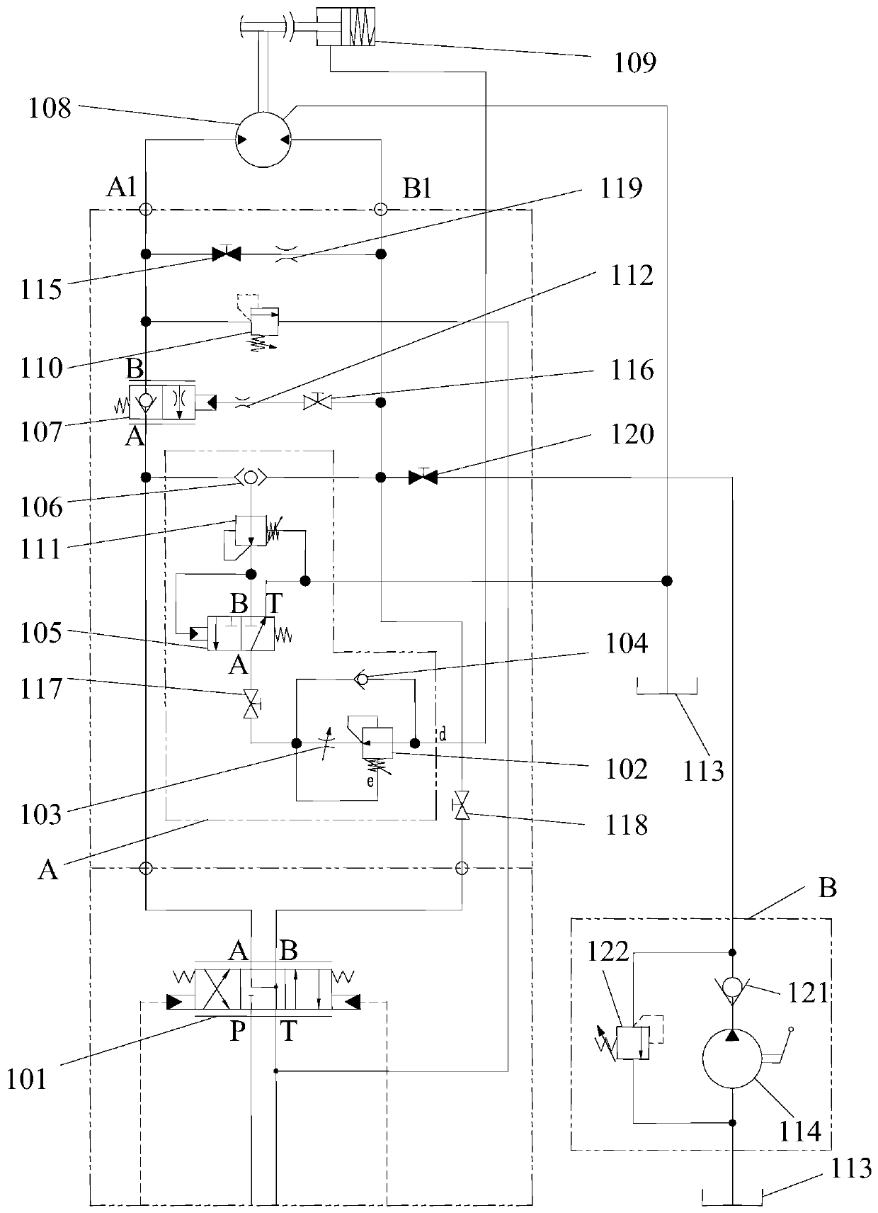
[0021] figure 1 A schematic diagram of a hydraulic control system of a crane provided in an embodiment of the present invention, as shown in figure 1 As shown, the hydraulic control system includes: a three-position four-way reversing valve 101, a hydraulic control module A, and the hydraulic control module A includes a differential pressure reducing valve 102, a first throttle valve 103, a first one-way valve 104, a hydraulic Control reversing valve 105, shuttle valve 106, balance valve 107, hydraulic motor 108 and brake cylinder 109.

[0022] The P port of the three-position four-way reversing valve 101 is connected with the oil inlet port of the hydraulic control system, the T port of the three-position four-way reversing valve 101...


PUM


Abstract

The invention discloses a hydraulic control system of a crane, and belongs to the field of control. A brake mechanism of a span winch is in a start state, and the span winch controls a lazy arm of thecrane to descend in an amplification manner. When the span winch needs to stop the descending process of the lazy arm of the crane, hydraulic oil in a rod cavity of a brake oil cylinder is pressed toflow towards a fixed differential reducing valve, a first throttling valve, a pilot operated directional control valve and an oil tank. The backflow speed of the hydraulic oil in the rod cavity of the brake oil cylinder is controllable through the fixed differential reducing valve and the first throttling valve, then the time that the pressure in the rod cavity of the brake oil cylinder is reduced till the span winch is locked by the brake mechanism is controllable, the time is the same as the time that the lazy arm of the crane gently descends by a section of distance under the inertia effect, and it is shown that when the lazy arm of the crane completes the descending motion under the inertia effect, the brake mechanism just brakes the span winch at this moment. The problems brought bytoo fast or slow braking of the brake mechanism are avoided, and the work efficiency of the crane is guaranteed.

Description

technical field [0001] The invention relates to the control field, in particular to a hydraulic control system of a crane. Background technique [0002] The boom of a large offshore crane is generally fixedly connected to the cable of the luffing winch of the crane, and the luffing winch controls the position of the boom of the crane by retracting and releasing the cable. A brake mechanism is installed on the luffing winch to lock the cables on the luffing winch when the luffing winch is not working, so as to ensure the stability of the boom position of the crane. The luffing winch and the braking mechanism on the crane are usually controlled by a hydraulic control system, which is used to control the luffing winch to retract and unwind the cables, and to control the braking mechanism to lock the luffing winch when the luffing winch is not working. cable. [0003] When the luffing winch releases the cable to make the boom of the crane increase and descend, if the release o...

Claims


Application Information

Patent Timeline
Patent Type & Authority Patents(China)
IPC IPC(8): B66C13/20B66C23/82B66D5/28F15B11/08
CPCB66C13/20B66C23/82B66D5/28F15B11/08
Inventor 程源丁元亮叶建
Owner WUHAN MARINE MACHINERY PLANT
Why Eureka
Try Eureka