
Method for measuring flow controlling particle density under simulated real reservoir conditions

A particle density and oil reservoir technology, applied in the direction of measuring devices, particle suspension analysis, suspension and porous material analysis, etc., can solve the problems of short particle migration distance, test particle density, and inability to meet construction needs, etc., to achieve improved results , Guarantee the effect of construction success rate

Inactive Publication Date: 2018-10-26
CHINA PETROLEUM & CHEM CORP
View PDF6 Cites 0 Cited by
  • Summary
  • Abstract
  • Description
  • Claims
  • Application Information

AI Technical Summary

Problems solved by technology

[0004] (1) There are many pores inside the flow-regulating particles during the processing process, resulting in a large difference between the density of the particles and the reservoir fluid density, resulting in a short migration distance of the particles, resulting in accumulation near the wellbore, which cannot meet the construction needs;
[0005] (2) At present, there is no instrument for testing particle density at high temperature and high pressure in China, which cannot ensure that the difference between the density of particles under reservoir conditions and the density of formation water is less than ±0.03g / cm 3

Method used


Image

  • Method for measuring flow controlling particle density under simulated real reservoir conditions
  • Method for measuring flow controlling particle density under simulated real reservoir conditions
  • Method for measuring flow controlling particle density under simulated real reservoir conditions

Examples


Embodiment Construction

[0038] Embodiments of the technical solutions of the present invention will be described in detail below in conjunction with the accompanying drawings. The following examples are only used to illustrate the technical solutions of the present invention more clearly, and therefore are only examples, rather than limiting the protection scope of the present invention.

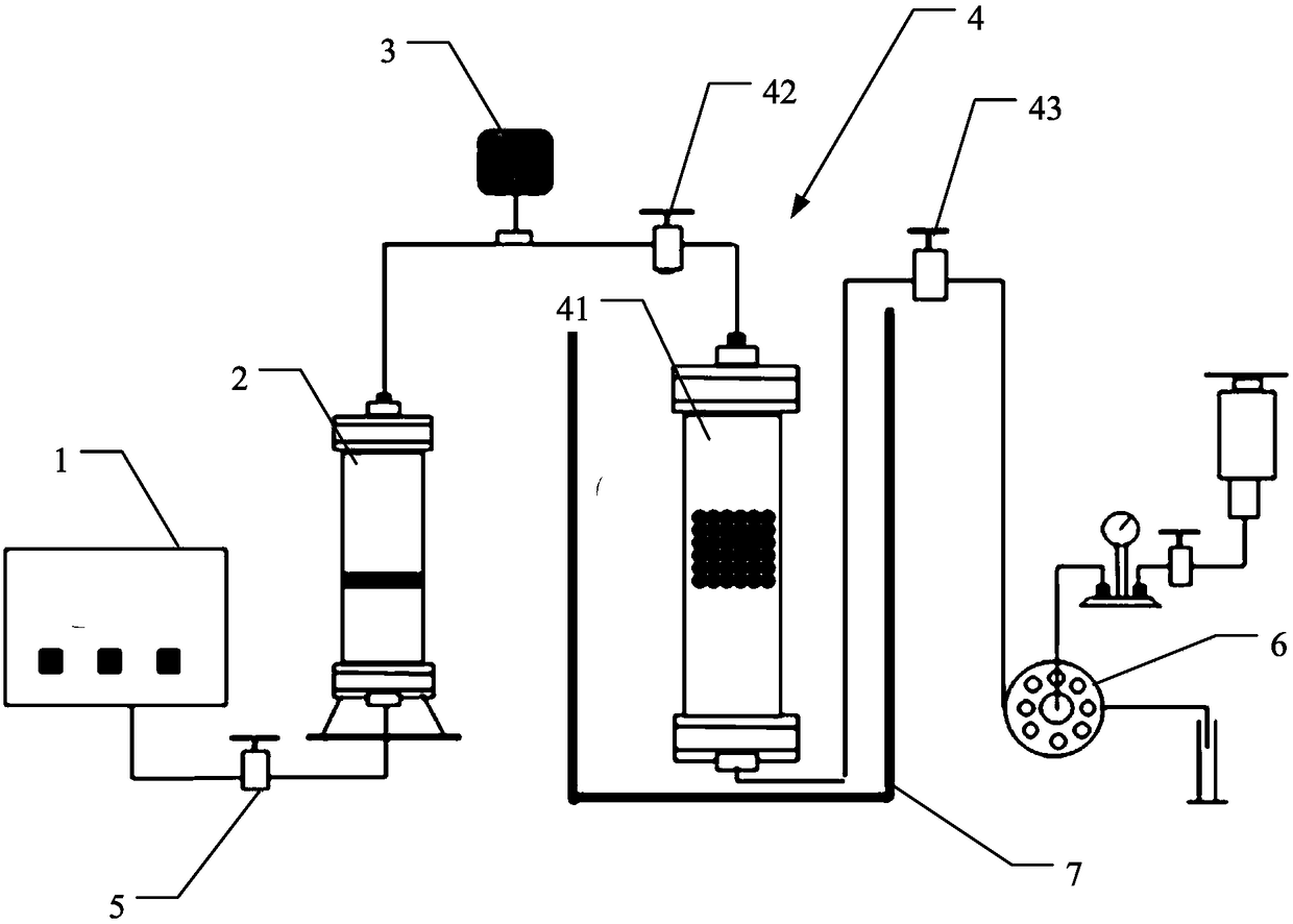
[0039] figure 1 A schematic structural diagram of a measurement system for measuring the density of flow-regulating particles under simulated real reservoir conditions is shown according to an embodiment of the present invention. Such as figure 1 As shown, the measurement system includes a liquid pump 1 , a piston container 2 and a simulation unit 4 , the liquid pump 1 is connected to the liquid inlet of the piston container 2 , and the liquid outlet of the piston container 2 is connected to the simulation unit 4 . The simulation unit 4 includes a simulation container 41 for containing reservoir simulation liquid...


PUM


Abstract

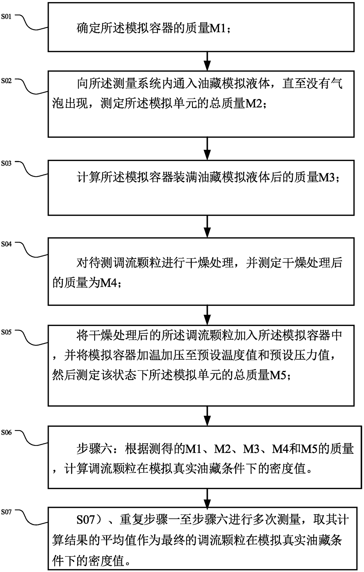
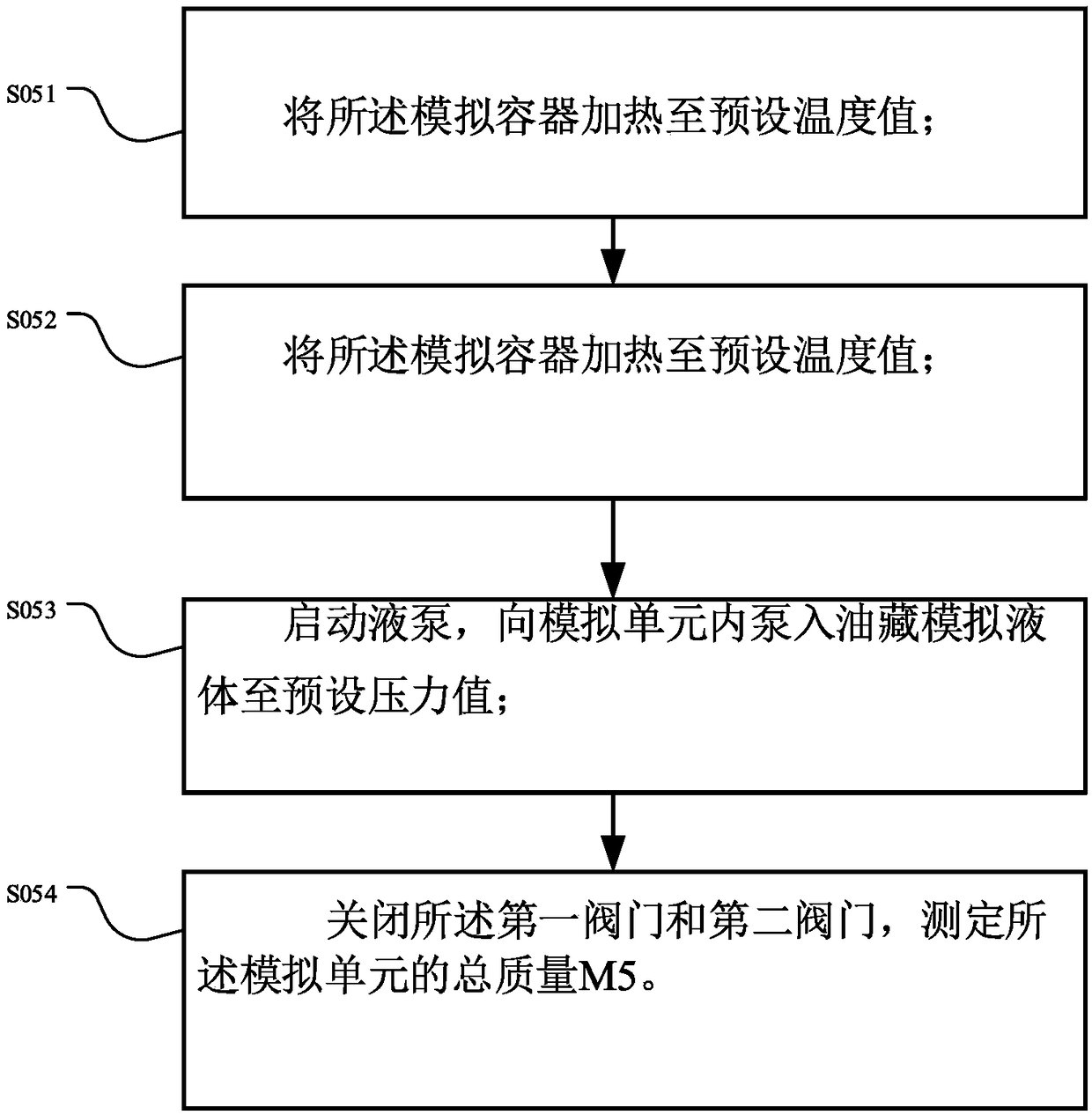
The invention discloses a method for measuring flow controlling particle density under simulated real reservoir conditions. The method comprises the following steps: step 1: determining the mass M1 ofthe simulated container; step 2: introducing a reservoir simulation liquid into the measuring system until no bubbles appear, and determining the total mass M2 of the simulation unit; step 3: calculating the mass M3 of the simulated container filled with the reservoir simulation liquid; step 4: drying the flow controlling particles to be treated and determining the mass M4 after drying; step 5: adding the dried treated flow controlling particles to the simulated container, and heating and pressing the simulated container to a preset temperature value and a preset pressure value, and then measuring the total mass M5 of the simulation unit in this state; step 6: calculating the density value of the flow controlling particles under simulated real reservoir conditions based on the measured masses of M1, M2, M3, M4 and M5. The measurement method can be measured under the real conditions of a simulated high temperature and high pressure reservoir, and the density of the particles under reservoir conditions can be tested.

Description

technical field [0001] The invention relates to the technical field of oil and gas exploitation, in particular to a method for measuring the flow-regulating particle density under simulated real oil reservoir conditions. Background technique [0002] The reservoir medium of Tahe fracture-cavity reservoir is composed of dissolved caves, fractures and dissolved pores, and the distribution is discontinuous. The injected water often flows in a certain direction in the formation, but does not reach other directions, resulting in poor water flooding effect. The recovery factor is only 17%. Flow channel adjustment technology is to place a certain amount of particles on the main channel of water channeling to realize the effect on the shrinkage joint of the dominant channel, activate the unused channels in the formation, and improve the water flooding effect. The injected material is called flow regulating particles. [0003] Flow regulating particles have the following problems: ...

Claims


Application Information

Patent Timeline
IPC IPC(8): G01N15/06
CPCG01N15/06
Inventor 赵海洋甄恩龙焦保雷钱真杨祖国巫光胜张佳袁飞宇田亮柏森何晓庆
Owner CHINA PETROLEUM & CHEM CORP
Learn More