Reactive power compensation device

A technology of power compensation and magnetic latching relay, which is applied in reactive power compensation, reactive power adjustment/elimination/compensation, circuit devices, etc., and can solve the problem that magnetic latching relays have offsets in closing time and off time and affect magnetic latching relays. And capacitor service life, high-frequency inrush current and other issues, to achieve the effect of suppressing high-frequency inrush current and overvoltage, improving service life and saving costs

Inactive Publication Date: 2018-10-26
NORTHEAST AGRICULTURAL UNIVERSITY
View PDF4 Cites 5 Cited by
  • Summary
  • Abstract
  • Description
  • Claims
  • Application Information

AI Technical Summary

Problems solved by technology

[0003] Existing reactive power compensation devices have been tested for zero-crossing switching before leaving the factory to achieve zero-crossing switching and ensure that there is no high-frequency inrush current and overvoltage during the switching process. Most of the methods are based on the operating environment before leaving the factory. The closing time of the holding relay coincides with the zero-crossing point of the grid voltage and the closing time coincides with the zero-crossing point of the capacitor current. After leaving the factory and applying it to the field, zero-crossing switching correction will no longer be performed, but the closing time and turning-off time of the magnetic latching relay are related to the drive voltage , grid voltage, grid frequency, temperature and the magnetic latching relay itself are all related. In different operating environments, the closing time and closing time of the magnetic latching relay will deviate, and high-frequency inrush current or overvoltage will occur during the switching process. Affect the service life of magnetic latching relays and capacitors

Method used


Image

  • Reactive power compensation device
  • Reactive power compensation device

Examples


Embodiment 1

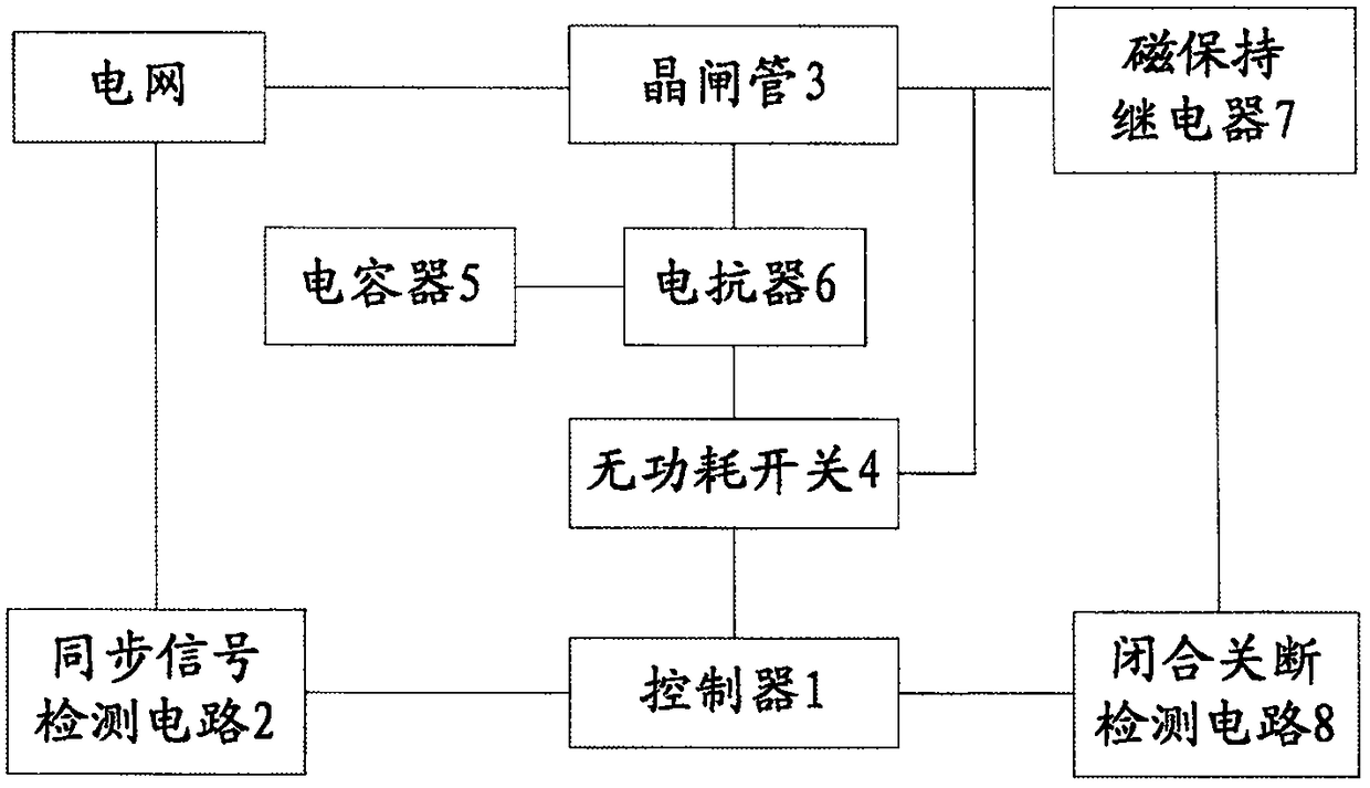
[0024] figure 1 It is a structural connection diagram of the reactive power compensation device of the present invention. Such as figure 1 As shown, the reactive power compensation device includes: a controller 1, a synchronous signal detection circuit 2, a thyristor 3, a non-power consumption switch 4, a capacitor 5, a reactor 6, a magnetic latching relay 7 and a closed-off detection circuit 8 ; The controller 1 is respectively connected with the synchronous signal detection circuit 2, the thyristor 3, the non-power consumption switch 4, the magnetic latching relay 7 and the closing and closing detection circuit 8, the thyristor 3 and the non-power consumption switch 4 are connected in parallel, and the thyristor 3 passes through the reactor 6 is connected with the capacitor 5; the magnetic latching relay 7 is connected with the thyristor 3.

[0025] The present invention can switch the capacitor group through the thyristor module when the voltage crosses zero, reducing the...

Embodiment 2

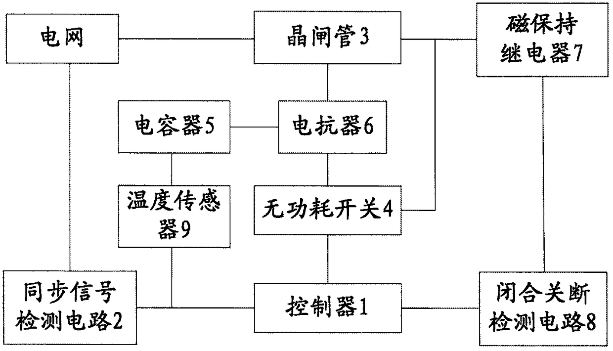
[0032] On the basis of Embodiment 1, the reactive power compensation device further includes a temperature sensor 9 , one end of the temperature sensor 9 is connected to the capacitor 5 , and the other end is connected to the controller 1 . The temperature sensor of the invention can monitor the online operation temperature of the capacitor in real time, so as to ensure the safe and reliable operation of the power grid.

Embodiment 3

[0034] On the basis of Embodiment 1, the synchronous signal detection circuit 2 of Embodiment 3 includes a signal conditioning circuit and a three-phase electric energy parameter acquisition module connected in sequence, the signal conditioning circuit is connected to the power grid, and the three-phase electric energy parameter acquisition module is connected to the controller 1 .


PUM


Abstract

The invention discloses a reactive power compensation device, and relates to the field of reactive power compensation. The reactive power compensation device comprises a controller, a synchronizing signal detection circuit, a thyristor, a non-power consumption switch, a capacitor, a magnetic latching relay, a close shutoff detection circuit and a reactor; the controller is connected with the synchronizing signal detection circuit, the thyristor, the non-power consumption switch, the magnetic latching relay and the close shutoff detection circuit; the thyristor is in a parallel connection withthe non-power consumption switch; the thyristor is connected with the capacitor through the reactor; the magnetic latching relay is connected with the thyristor; and according to the synchronizing signal detected by the synchronizing signal detection circuit and the close or shutoff time of the magnetic latching relay detected by the lose shutoff detection circuit, the controller acquires a comparative result and rectifies the drive time of the magnetic latching relay according to the comparative result. The reactive power compensation device provided by the invention can effectively restrainthe high frequency flow and the overvoltage; when the device runs for a long time, the capacitor can be connected at the passing zero time of the voltage or disconnected at the passing zero time of the current; and thus, the service life of the magnetic latching relay and the capacitor is prolonged.

Description

technical field [0001] The invention relates to the field of reactive power compensation, in particular to a reactive power compensation device. Background technique [0002] Reactive power often exists in the low-voltage distribution network. Reactive power reduces the user power factor, increases line and equipment losses, and reduces user voltage; increases the total current, which increases the capacity of components in the power system and increases investment; increases the voltage loss of lines and transformers. Therefore, it is of great significance to improve the power factor of the power grid and improve the quality of power grid operation. The application of reactive power compensation technology in power grid is more and more extensive. [0003] Existing reactive power compensation devices have been tested for zero-crossing switching before leaving the factory to achieve zero-crossing switching and ensure that there is no high-frequency inrush current and overv...

Claims


Application Information

Patent Timeline
Patent Type & Authority Applications(China)
IPC IPC(8): H02J3/18
CPCH02J3/1864Y02E40/30
Inventor 房俊龙甄景龙高三策聂语李素旋
Owner NORTHEAST AGRICULTURAL UNIVERSITY
Why Eureka
Try Eureka