Smart Capacitors for On-Site Zero-Crossing Switching Correction

A technology of zero-crossing switching and capacitors, which is applied in reactive power compensation, reactive power adjustment/elimination/compensation, etc., can solve the problem of parameter changes. Meet the problems of suppressing inrush current and overvoltage, unable to correct the zero-crossing switching time, etc., to achieve the effects of suppressing high-frequency inrush current and overvoltage, improving service life and saving costs

Inactive Publication Date: 2017-10-13
NORTH CHINA ELECTRIC POWER UNIV (BAODING)
View PDF2 Cites 0 Cited by
  • Summary
  • Abstract
  • Description
  • Claims
  • Application Information

AI Technical Summary

Problems solved by technology

[0005] The existing smart capacitors based on magnetic latching relays have been tested for zero-crossing switching before leaving the factory, and zero-crossing switching has been realized, ensuring that there is no high-frequency inrush current and overvoltage in the switching process, but the closing time and closing time of the magnetic latching relay It is related to the driving voltage, grid voltage, grid frequency, temperature and the magnetic latching relay itself. In different operating environments, the closing time and closing time of the magnetic latching relay will deviate. Uncertain parameter changes make the magnetic latching relay It is not easy to control the zero-crossing closure or zero-crossing shutdown, and high-frequency inrush current or overvoltage will occur during the switching process, especially after the smart capacitor has been operated on site for a long time, the zero-crossing closure or zero-crossing shutdown moment of the magnetic latching relay will be Variety
Therefore, the existing smart capacitors cannot correct the zero-crossing switching time based on the field operating environment, and cannot well meet the needs of suppressing inrush current and overvoltage

Method used


Image

  • Smart Capacitors for On-Site Zero-Crossing Switching Correction
  • Smart Capacitors for On-Site Zero-Crossing Switching Correction

Examples


Embodiment Construction

[0014] The present invention provides an intelligent capacitor for on-site zero-crossing switching correction. The present invention will be further described below through the description of the drawings and specific implementation methods.

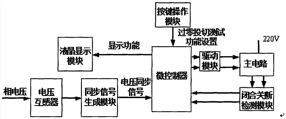
[0015] Take phase a zero-crossing switching correction as an example to illustrate, figure 1 It is a schematic structural diagram of the phase a of the intelligent capacitor for on-site zero-crossing switching correction of the present invention. module and main circuit. The zero-crossing and switching correction function is added in the single-chip microcomputer program. The function is displayed by the liquid crystal display module, and the function is input by the key operation module. When the zero-crossing correction function is selected, the single-chip microcomputer zero-crossing and switching correction program is entered.

[0016] figure 1 The detected a-phase voltage signal is compared with zero crossing to generate a synchro...


PUM


Abstract

The invention belongs to the technical field of reactive power compensation equipment, in particular to an intelligent capacitor for on-site zero-crossing switching correction. The smart capacitor is composed of a liquid crystal display module, a key operation module, a voltage transformer, a synchronous signal generation module, a microcontroller, a magnetic latching relay drive module, a closing and breaking detection module and a main circuit. The microcontroller completes the setting of the zero-crossing switching correction function through the liquid crystal display module and the key operation module. The microcontroller detects the synchronous signal of the phase voltage, and the on-off detection module detects the on-off state of the main circuit, generates a feedback signal and inputs it to the microcontroller, and the microcontroller corrects the driving time after judging the deviation of the zero-crossing time to ensure that the smart capacitor is over Zero switching capacitance. The present invention corrects the zero-crossing switching time by the user's operation on site, suppresses surge current and overvoltage, and improves the service life of the intelligent capacitor.

Description

technical field [0001] The invention belongs to the technical field of reactive power compensation equipment, in particular to an intelligent capacitor for on-site zero-crossing switching correction. Background technique [0002] Most of the load types in the power system are resistive and inductive, and power companies generally use power electronic equipment extensively, which makes the power factor of the power grid low. The lower power factor reduces the utilization rate of equipment, increases power supply investment, reduces the service life of equipment, and greatly increases line loss. After the capacitors are connected in parallel, the current of the capacitor will offset part of the inductor current, so that the total current is reduced, the phase difference between the voltage and the current becomes smaller, and the power factor is improved. It is of great significance to strengthen and improve the reactive power compensation status of distribution network, and ...

Claims


Application Information

Patent Timeline
Patent Type & Authority Patents(China)
IPC IPC(8): H02J3/18
CPCY02E40/30
Inventor 赵国鹏王彦杰韩民晓
Owner NORTH CHINA ELECTRIC POWER UNIV (BAODING)
Why Eureka
Try Eureka