Heat dissipation and dust removal device for electromechanical equipment

A technology of electromechanical equipment and dust removal device, which is applied to the construction of electrical equipment components, smoke and dust removal, cleaning methods using tools, etc., can solve problems such as dust prone to failure, affect heat dissipation effect, and ignore dust removal, etc., to protect the environment , Improve the heat dissipation effect and reduce the temperature effect

Pending Publication Date: 2018-10-30
SHANGHAI UNIV OF MEDICINE & HEALTH SCI
View PDF2 Cites 7 Cited by
  • Summary
  • Abstract
  • Description
  • Claims
  • Application Information

AI Technical Summary

Problems solved by technology

Electromechanical equipment will generate a large amount of heat energy during the processing and production process. If the heat cannot be conducted in time, it will easily cause equipment damage.
And some mechanical and electrical equipment have very precise internal structure, if too much dust enters, it will be prone to failure
Some of the existing device cooling devices use fan blowing for heat dissipation. There will be dust hanging on the filter at the vent, and long-term accumulation will affect the blowing efficiency of the fan, thereby affecting the heat dissipation effect. Therefore, the filter on the cooling device needs to be cleaned from time to time dust removal, which increases maintenance costs and wastes manpower and material resources, while the existing electromechanical cooling devices generally ignore the dust removal treatment

Method used


Image

  • Heat dissipation and dust removal device for electromechanical equipment
  • Heat dissipation and dust removal device for electromechanical equipment

Examples


Embodiment 1

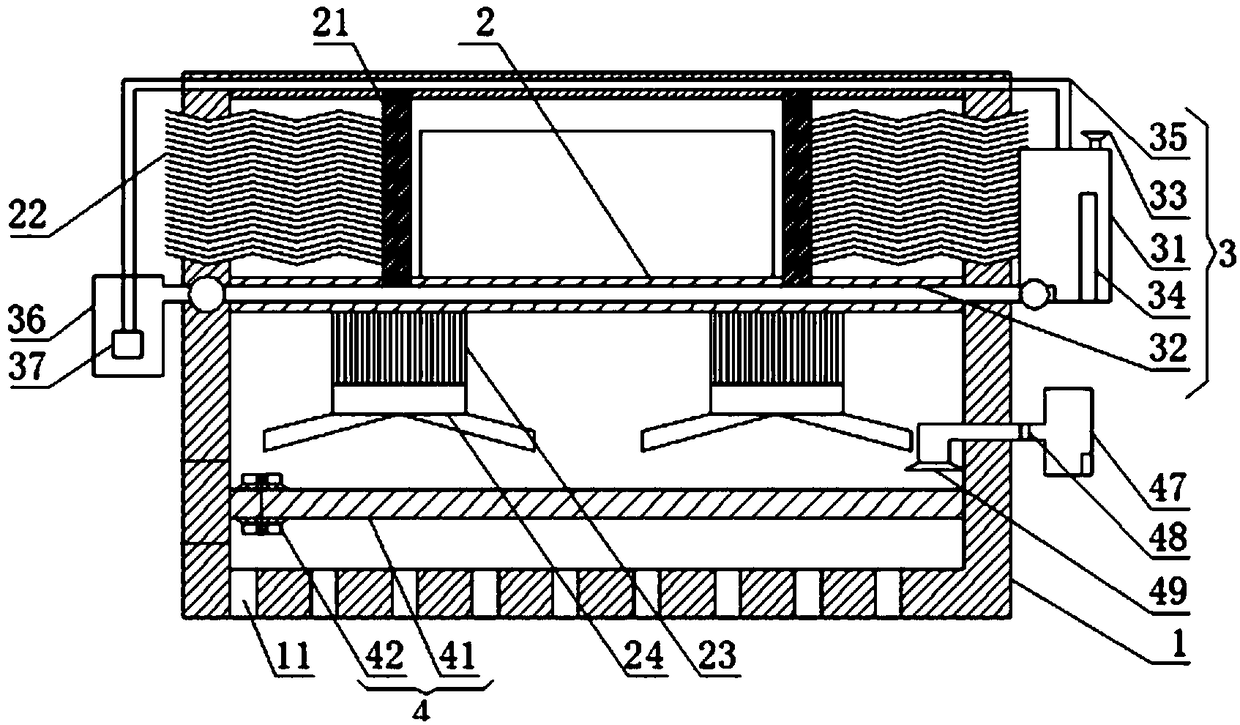
[0028] A heat dissipation and dust removal device for electromechanical equipment, its structure is as follows figure 1 , figure 2 As shown, including the shell 1, the inner wall of the bottom plate of the shell 1 is separately provided with several through holes 11, and the heat can be discharged from the through holes 11. The inner cavity side wall of the shell 1 is fixedly installed with a mounting plate 2, and 2 is a metal heat-conducting material, and the top outer wall of the mounting plate 2 is symmetrically fixed with two side plates 21, and a number of heat-conducting wires 22 are fixedly installed on the side of the two side plates 21 close to the shell 1, and each heat-conducting wire 22 is wavy. In addition, the end of each heat conducting wire 22 away from the side plate 21 extends to the outside through the shell 1, the heat conducting wire 22 can improve the heat dissipation effect of the side plate 21, and the tops of the two side plates 21 are fixedly connect...


PUM


Abstract

The invention relates to a heat dissipation and dust removal device for electromechanical equipment. The head dissipation and dust removal device comprises a shell, heat dissipation units, a heat conducting unit and a dust removal unit; a horizontally-arranged hollow installation plate is fixedly installed in the middle of the shell, two side plates are fixed to the top of the installation plate,and the side plates, the installation plate and the shell jointly form a space for containing the electromechanical equipment; the heat dissipation units comprises first heat dissipation units arranged on the side plates and second heat dissipation units fixedly arranged at the bottom of the installation plate; the heat conducting unit is cyclically arranged on the upper portion of the shell, andcooling liquid cyclically flows in the heat conducting unit; the dust removal unit comprises a dust removal net, a detachable sweeping unit for sweeping dust accumulated on the dust removal net and adust suction unit for sucking dust. Compared with the prior art, by means of the heat dissipation and dust removal device, the electromechanical equipment can achieve the advantages of being good in dust removal and heat dissipation effect and the like.

Description

technical field [0001] The invention relates to the technical field of electromechanical equipment, in particular to a heat dissipation and dust removal device for electromechanical equipment. Background technique [0002] With the development of reform and opening up, my country has entered the era of industrialization, and electromechanical equipment is a must in the manufacturing industry. Electromechanical equipment will generate a large amount of heat energy during the processing and production process. If the heat cannot be conducted in time, it will easily cause equipment damage. Moreover, some electromechanical equipment have very precise internal structures, and if too much dust enters, it will be prone to failure. Some of the existing device cooling devices use fan blowing for heat dissipation. There will be dust hanging on the filter at the vent, and long-term accumulation will affect the blowing efficiency of the fan, thereby affecting the heat dissipation effec...

Claims


Application Information

Patent Timeline
Patent Type & Authority Applications(China)
IPC IPC(8): H05K7/20B08B1/00B08B15/04
CPCH05K7/20136H05K7/20218H05K7/20409B08B1/002B08B1/008B08B15/04
Inventor 黄钢俞凯君罗宇舟
Owner SHANGHAI UNIV OF MEDICINE & HEALTH SCI
Why Eureka
Try Eureka