Eureka AIR delivers breakthrough ideas for toughest innovation challenges, trusted by R&D personnel around the world.

Noise reduction type drilling equipment for steel machining

A kind of drilling equipment and noise reduction technology, which is applied in the field of drilling equipment for noise reduction steel processing, can solve the problems of insufficient matching of components, increase the cost of equipment use, short service life of drill bits, etc., so as to reduce collision and prolong use. The effect of life and maintenance of the use environment

Inactive Publication Date: 2018-11-02
杨玲玲
View PDF4 Cites 17 Cited by
  • Summary
  • Abstract
  • Description
  • Claims
  • Application Information

AI Technical Summary

Problems solved by technology

[0002] Hardware drilling equipment is an auxiliary device used for drilling hardware parts during production and processing, and it is widely used in the processing field; existing hardware drilling equipment includes workbenches and drilling machines, drilling During the drilling process, due to the mutual contact of the equipment and the operation of the equipment itself, the vibration of the equipment generates a lot of noise, especially for some equipment that has been used for a long time and the parts are not well matched. The noise is large and the operator feels uncomfortable. , which is not conducive to the use of equipment; in addition, when drilling hardware, the temperature of the drill bit is seldom cooled, resulting in a short service life of the drill bit, which needs to be replaced frequently and increases the cost of equipment use. Improvement to solve the above problems

Method used


Image

  • Noise reduction type drilling equipment for steel machining
  • Noise reduction type drilling equipment for steel machining
  • Noise reduction type drilling equipment for steel machining

Examples


Embodiment Construction

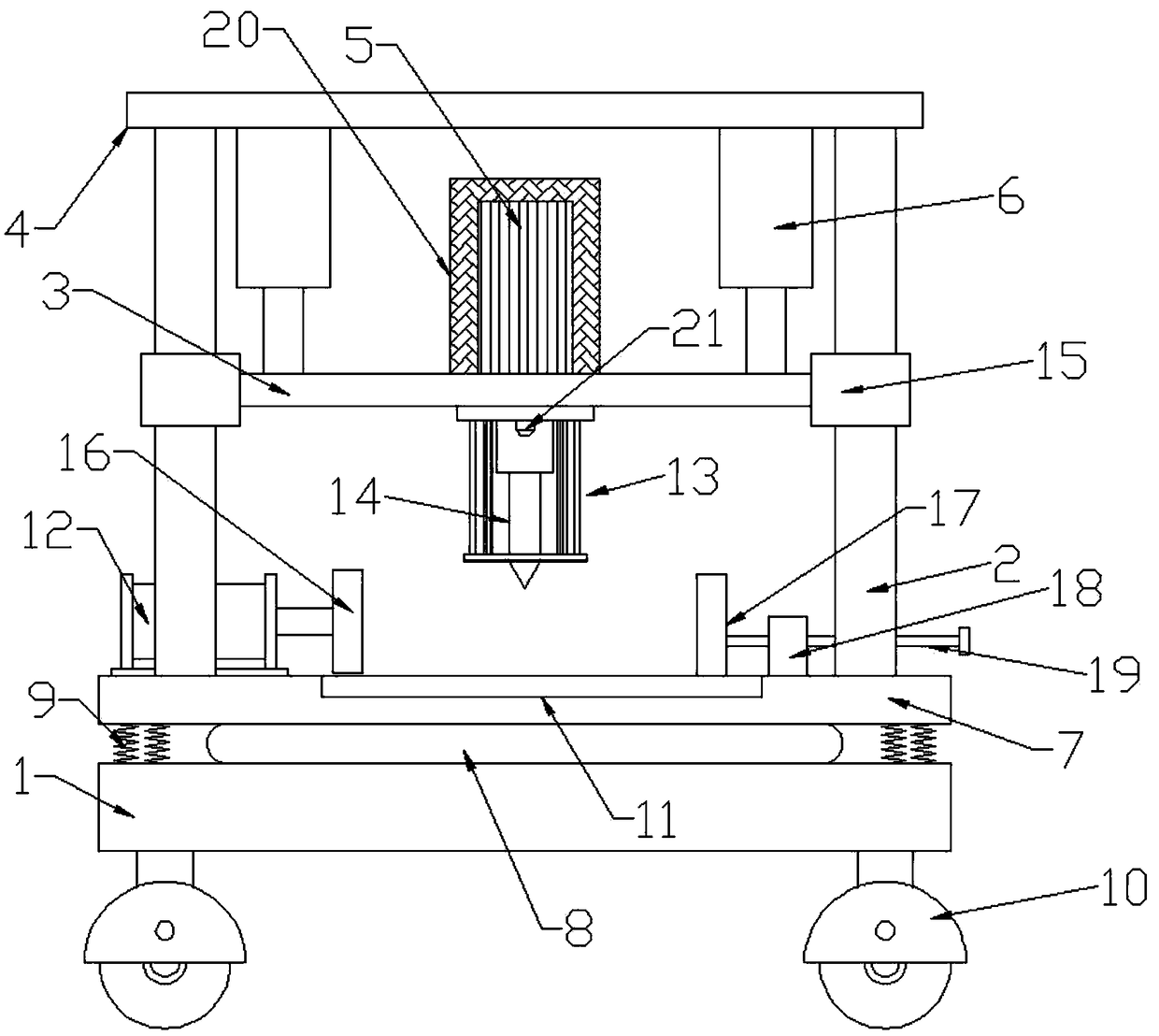
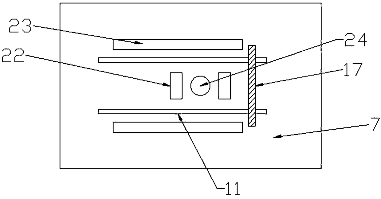
[0018] Please refer to the figure, in the embodiment of the present invention, a kind of drilling equipment for noise-reducing steel processing includes a base 1, a column 2, a lifting beam 3, a top plate 4, a motor 5 and a mounting plate 7; the lower side of the base 1 Rollers 10 are installed to facilitate equipment movement; the mounting plate 7 is located above the base 1, and a shock-absorbing air bag 8 and a shock-absorbing spring 9 are arranged between the base 1 and the mounting plate 7, and the upper and lower parts of the shock-absorbing air bag 8 are respectively glued Attached to the mounting plate 7 and the base 1, the shock absorbing spring 9 is provided with several, the upper end is fixed on the mounting plate 7, the lower end is fixed on the base 1, the mounting plate 7 is supported by the shock absorbing air bag 8 and the shock absorbing spring 9, and the The pressure exerted on the base 1 plays the role of shock absorption and buffering.

[0019] Both ends o...


PUM


Abstract

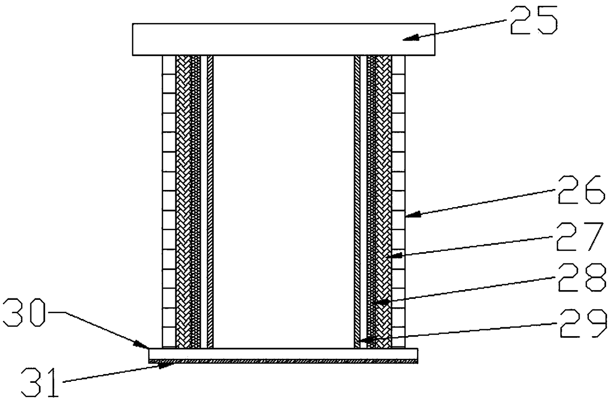
The invention discloses noise reduction type drilling equipment for steel machining. The noise reduction type drilling equipment comprises a base, vertical columns, a lifting beam, a top plate, a motor and a mounting plate. A shock absorption airbag and shock absorption springs are arranged between the base and the mounting plate. A waterproof noise reduction cylinder fixed to the lifting beam isarranged on the outer side of a drill bit in a sleeving mode. A downward spray nozzle is mounted on the corresponding lifting beam and arranged in the waterproof noise reduction cylinder. A noise reduction cover is arranged on the outer side of the motor in a covering mode. A first movable clamping board and a second movable clamping board are separately disposed on the left and right sides of a drill bit hole. Through the shock absorption airbag and the shock absorption springs disposed between the mounting plate and the base, vibration generated during operation is greatly reduced and noiseis reduced; and a soundproof layer in the waterproof noise reduction cylinder can reduce noise generated during drilling, the noise is in waterproof noise reduction cylinder and cannot be transmittedoutward so as to realize noise reduction, and meanwhile, the noise reduction cover disposed on the outer side of the motor reduces the noise generated when the motor runs.

Description

technical field [0001] The invention relates to the field of hardware processing, in particular to a drilling device for processing noise-reducing steel materials. Background technique [0002] Hardware drilling equipment is an auxiliary device used for drilling hardware parts during production and processing, and it is widely used in the processing field; existing hardware drilling equipment includes workbenches and drilling machines, drilling During the drilling process, due to the mutual contact of the equipment and the operation of the equipment itself, the vibration of the equipment generates a lot of noise, especially for some equipment that has been used for a long time and the parts are not well matched. The noise is large and the operator feels uncomfortable. , which is not conducive to the use of equipment; in addition, when drilling hardware, the temperature of the drill bit is seldom cooled, resulting in a short service life of the drill bit, which needs to be re...

Claims


Application Information

Patent Timeline
IPC IPC(8): B23B39/00B23Q3/06B23Q11/08B23Q11/10
CPCB23B39/00B23Q3/06B23Q11/08B23Q11/1015
Inventor 杨玲玲
Owner 杨玲玲
Why Eureka
Eureka Blog
Learn More