Wire harness conveying device

A wire feeding device and wire harness technology, which is applied in the field of wire harness processing, can solve the problems of wire harness knotting, lack of tension, and wire harness staggering, and achieve the effects of avoiding impact, avoiding wear or scratches, and increasing friction

Inactive Publication Date: 2018-11-02
WUHU BOKANG ELECTRICAL
View PDF6 Cites 4 Cited by
  • Summary
  • Abstract
  • Description
  • Claims
  • Application Information

AI Technical Summary

Problems solved by technology

At present, in the modern wire harness processing industry, the existing wire feeding operation is often passive wire feeding, that is, the wire harness needs to be pulled through other structures, and the length and speed of wire feeding cannot be accurately controlled.
[0003] Chinese Patent Application Publication No. CN107123954A discloses a clamping device for wire harness stripping, including a pay-off stand and a take-up stand. The pay-off stand only carries the wire harness to be processed. After the wire is completed, the wire harness lacks tension when it is sent out. Therefore, the wire feeding mechanism often has the problems of wire harness interlacing and wire harness knotting during the actual wire feeding process.
[0004] The Chinese patent application publication number is CN104071635A discloses a wire harness feeding device, including a base, a horizontal wire inlet channel, a pulley block and a measuring scale, the base is provided with a horizontal wire inlet channel and a measuring scale, and the horizontal wire inlet channel A pulley block is provided, the pulley block is connected to the motor, the base is provided with several horizontal wire inlet channels, the horizontal wire inlet channel is provided with a wire slot, and the wire inlet slot is provided with a wire harness induction sensor. Controlled, and the speed is adjustable; a wire harness wire feeding device provided by the present invention can separate wires of different colors and wire numbers by providing several horizontal wire inlet channels, which is convenient for actual operation and improves work efficiency; The wiring harness wire feeding device can determine the wire feeding length through the setting of the pulley block and the measuring scale, and output stably; the wire harness feeding device can automatically stop working once problems such as wire jamming, knotting, and wireless problems occur through the setting of the wire harness induction sensor And give an alarm, but the structure of the whole device is too complicated and takes up a lot of space

Method used


Image

  • Wire harness conveying device
  • Wire harness conveying device
  • Wire harness conveying device

Examples


Embodiment 1

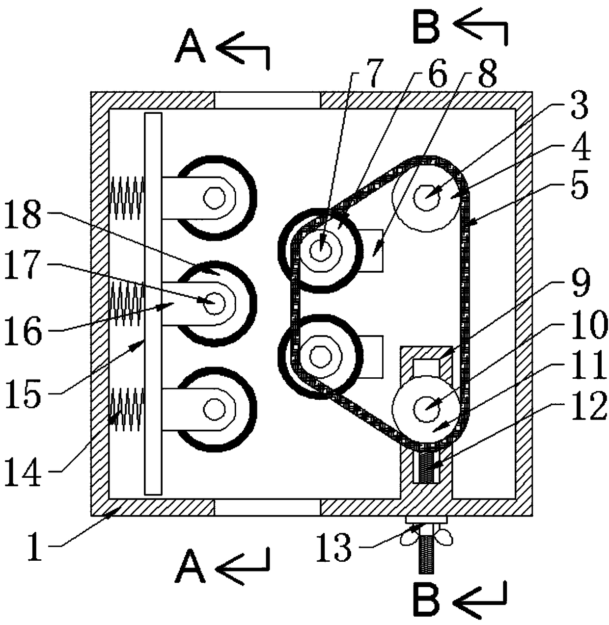
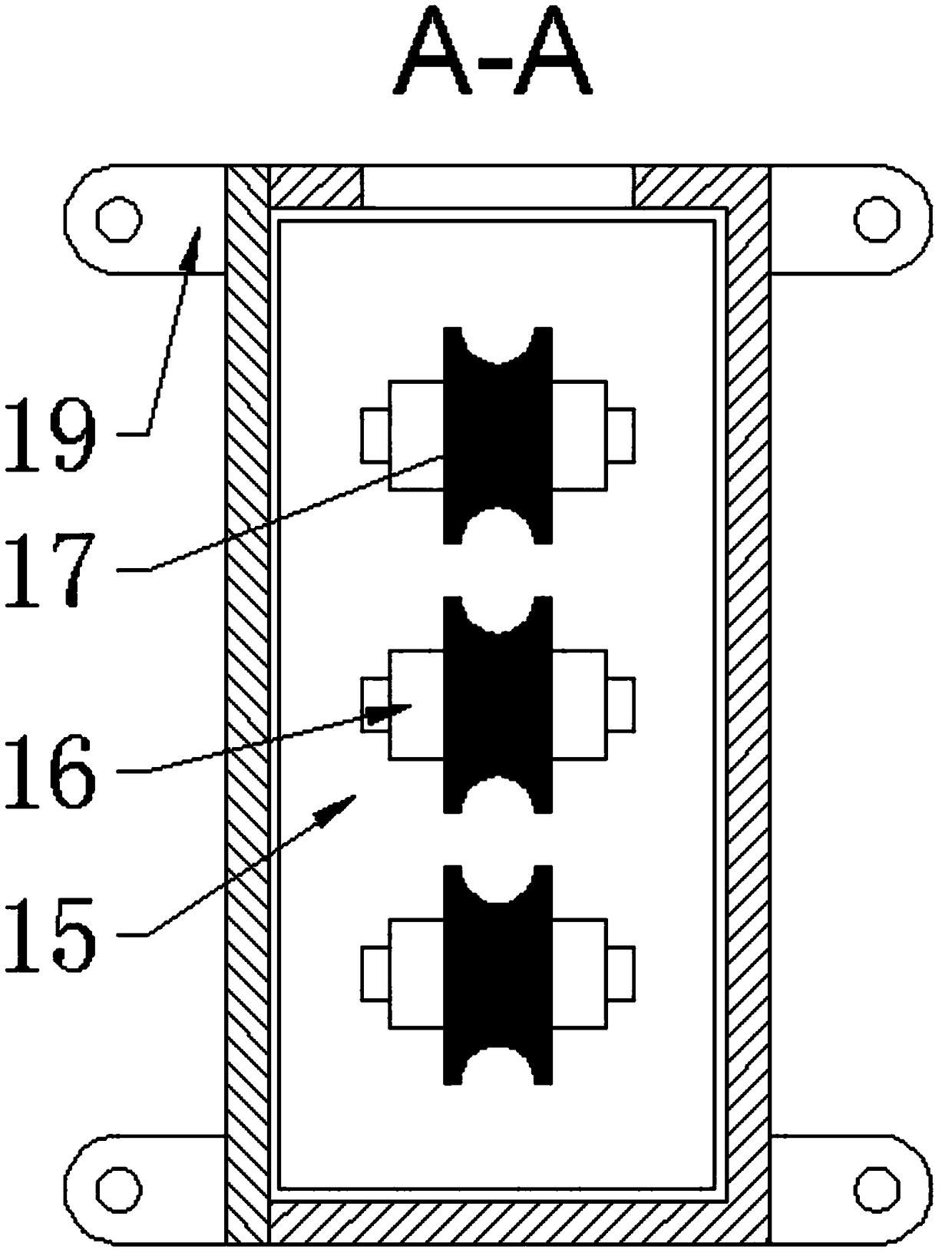
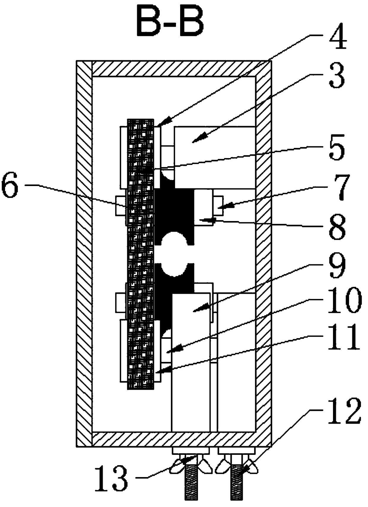
[0024] Such as Figure 1 to Figure 5 As shown, it includes a housing 1 and an adjustment assembly and a drive assembly installed inside the housing 1. The adjustment assembly includes a spring 14 and a movable plate 15. One end of the spring 14 is connected to the housing 1, and the other end is connected to the movable plate 15. connection, the movable plate 15 is provided with a support plate three 16 and a support column three 17, and the support column three 17 is rotatably connected with an auxiliary wire feeding wheel 18 and is installed on the support plate three 16; the drive assembly includes a motor 3 and Drive wheel 4, the motor 3 is vertically installed on the bottom of the housing 1, the drive wheel 4 is installed on the rotating shaft of the motor 3, the drive wheel 4 is connected with the wire feeding pulley 6 and the tension pulley 11 through the belt 5, the shell The left side inside the body 1 is also provided with a support column one 7, a support plate one ...

Embodiment 2

[0031] Such as Figure 1 to Figure 5 As shown, it includes a housing 1 and an adjustment assembly and a drive assembly installed inside the housing 1. The adjustment assembly includes a spring 14 and a movable plate 15. One end of the spring 14 is connected to the housing 1, and the other end is connected to the movable plate 15. connection, the movable plate 15 is provided with a support plate three 16 and a support column three 17, and the support column three 17 is rotatably connected with an auxiliary wire feeding wheel 18 and is installed on the support plate three 16; the drive assembly includes a motor 3 and Drive wheel 4, the motor 3 is vertically installed on the bottom of the housing 1, the drive wheel 4 is installed on the rotating shaft of the motor 3, the drive wheel 4 is connected with the wire feeding pulley 6 and the tension pulley 11 through the belt 5, the shell The left side inside the body 1 is also provided with a support column one 7, a support plate one ...


PUM


Abstract

The invention discloses a wire harness conveying device. The wire harness conveying device comprises a housing; a regulating part of the wire harness conveying device is installed at the internal leftpart of the housing; a driving part of the wire harness conveying device is installed at the internal right part of the housing; the regulating part comprises a spring; one end of the spring is connected with the housing; the other end is connected with a movable plate; the movable plate is provided with a supporting plate and a supporting column; the supporting column is rotationally connected with an auxiliary wire conveying wheel and is installed on the supporting plate; the driving part comprises a motor; the motor is vertically installed at the bottom of the housing; a driving wheel is installed at the rotating shaft of the motor and is connected with a wire conveying wheel and a tensioning wheel through a belt; the tensioning wheel is regulated by virtue of a screw rod and a regulating nut; the upper end face and the lower end face of the housing are each provided with a through hole; and the through holes are correspondingly used as a wire inlet and a wire outlet for wire harnesses. The wire harness conveying device disclosed by the invention realizes orderly send-out of to-be-processed wire harnesses by arranging the wire conveying wheel and the auxiliary wire conveying wheel between a wire conveying opening and the wire outlet.

Description

technical field [0001] The invention relates to the technical field of wire harness processing, in particular to a wire harness feeding device. Background technique [0002] The wiring harness is the wiring part that connects various electrical equipment in the circuit, and is composed of insulating sheaths, terminal blocks, wires and insulating wrapping materials. At present, in the modern wire harness processing industry, the existing wire feeding operation is often passive wire feeding, that is, the wire harness needs to be pulled through other structures, and the length and speed of wire feeding cannot be precisely controlled. [0003] Chinese Patent Application Publication No. CN107123954A discloses a clamping device for wire harness stripping, including a pay-off stand and a take-up stand. The pay-off stand only carries the wire harness to be processed. After the wire is completed, the wire harness lacks tension when it is sent out. Therefore, the wire feeding mechani...

Claims


Application Information

Patent Timeline
IPC IPC(8): B65H51/08B65H59/10
CPCB65H51/08B65H59/10B65H2701/34
Inventor 朱磊马能发李华郑凯邱亮亮施其兵方良周前宽张冲张静冯瑞叶立新张建军杨开文
Owner WUHU BOKANG ELECTRICAL
Why Eureka
Try Eureka