Oil pan having small active volume oil reservoir and methods of using the same

A technology of oil reservoir and oil tank, which is applied in the direction of oil pan, machine/engine, engine lubrication, etc.

Active Publication Date: 2018-11-02
GM GLOBAL TECH OPERATIONS LLC
View PDF3 Cites 0 Cited by
  • Summary
  • Abstract
  • Description
  • Claims
  • Application Information

AI Technical Summary

Problems solved by technology

Thermal management of ICE and engine oil remains a challenge, especially during ICE cold starts

Method used


Image

  • Oil pan having small active volume oil reservoir and methods of using the same
  • Oil pan having small active volume oil reservoir and methods of using the same
  • Oil pan having small active volume oil reservoir and methods of using the same

Examples


Embodiment Construction

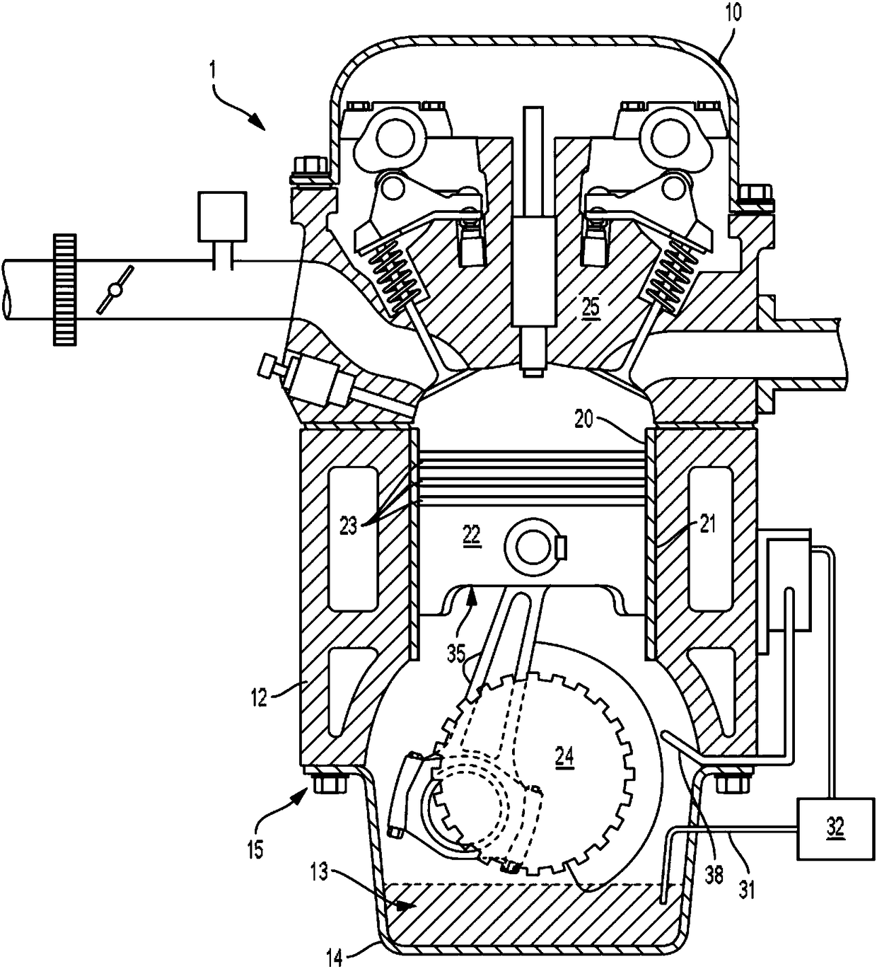
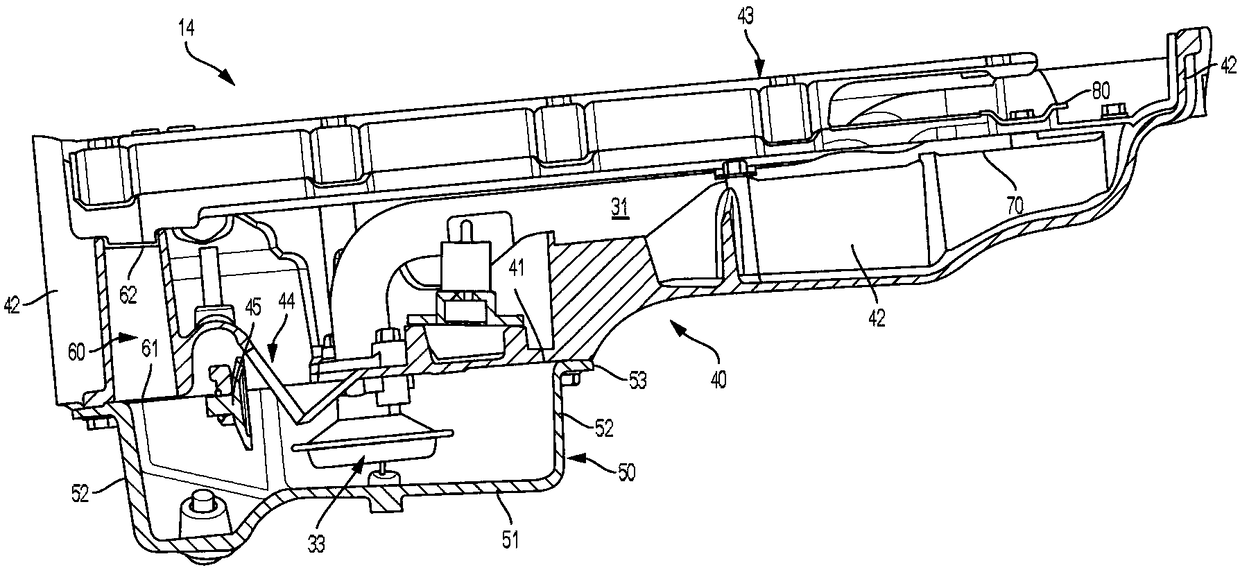
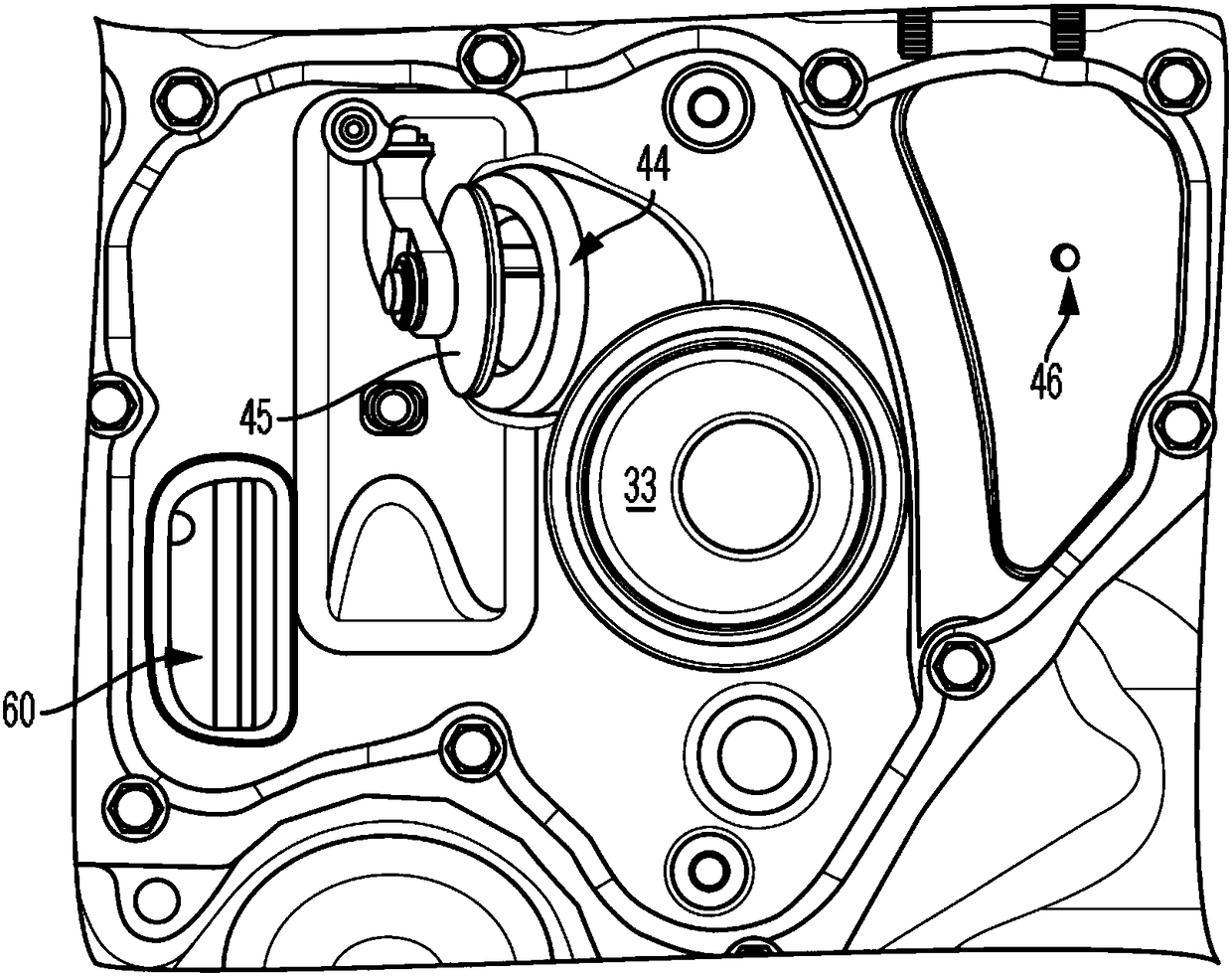
[0014] Embodiments of the disclosure are described herein. It should be understood, however, that the disclosed embodiments are merely examples and that other embodiments may take various alternative forms. The figures are not necessarily to scale; some features may be exaggerated or minimized to show details of particular components. Therefore, specific structural and functional details disclosed herein are not to be interpreted as limiting, but merely as a representative basis for teaching one skilled in the art to variously employ the present invention. As will be understood by persons of ordinary skill in the art, various features shown and described with reference to any one figure can be combined with features shown in one or more other figures to create embodiments not explicitly shown or described . Combinations of features shown provide representative embodiments for typical applications. However, various combinations and modifications of the features consistent wi...


PUM


Abstract

Provided are oil reservoirs and engine oil circulation systems including an upper sump capable of receiving oil from an engine, a lower sump disposed vertically below the upper sump, a valve-controlled orifice (VCO) penetrating the upper sum bottom, an oil chimney capable of receiving oil and communicating oil to the lower sump, and an oil conduit capable of extracting oil from the lower sump. Methods for operating systems include maintaining the VCO in an open position for a draw down duration temporally proximate an engine cold start, subsequently circulating oil between the engine and the oil reservoir, actuating the VCO to a closed position subsequent to the draw down duration for a warmup duration, and actuating the VCO to an open position subsequent to the warmup duration. Methods can further include actuating the VCO to an open position during the warmup duration in response to an increased oil demand event.

Description

Background technique [0001] The oil pan collects the oil used to lubricate the internal combustion engine. During operation of an internal combustion engine (ICE), oil may circulate within the engine to lubricate its moving parts, dissipate thermal energy, and prevent wear of the ICE. After lubricating the moving parts of the engine, the oil is collected by the oil pan. Thermal management of ICE and engine oil remains a challenge, especially during ICE cold starts. Contents of the invention [0002] In one or more embodiments, an oil reservoir is provided that includes an upper oil sump, a lower oil sump, a valve control orifice, an oil conduit, an oil pump conduit; the upper oil sump is defined by the sump bottom and one or more side walls and includes a an at least partially open top end receiving oil, the lower sump disposed vertically below the upper sump, including the top end adjoining at least a portion of the bottom of the upper sump, the valve control orifice pass...

Claims


Application Information

Patent Timeline
Patent Type & Authority Applications(China)
IPC IPC(8): F01M1/02F01M1/16F01M5/02F01M11/00
CPCF01M1/02F01M1/16F01M5/02F01M11/0004F01M2011/0087F01M2011/0045F01M2011/007F01M11/0408F01M2005/023F01M2011/0033
Inventor B·J·赫克曼A·W·海曼
Owner GM GLOBAL TECH OPERATIONS LLC
Why Eureka
Try Eureka