Oil-gas separating structure and engine

A separation structure and engine technology, which is applied in the direction of engine components, machines/engines, mechanical equipment, etc., can solve the problems that the oil-gas separation rate cannot meet the demand, the oil-gas separation efficiency cannot be balanced, and the blow-by flow rate cannot reach the predetermined value, etc., to achieve stability Oil and gas separation efficiency, reduced layout space requirements, and simple structure

Active Publication Date: 2018-11-02
BEIQI FOTON MOTOR CO LTD
View PDF9 Cites 2 Cited by
  • Summary
  • Abstract
  • Description
  • Claims
  • Application Information

AI Technical Summary

Problems solved by technology

However, whether it is a cyclone or a baffle structure, the required separation efficiency can only be achieved when the blow-by flow rate reaches a predetermined value.
Therefore, when the engine is running at a small speed, the flow rate of the blow-by gas cannot reach the predetermined value. In this case, the oil-gas separation rate cannot meet the demand
[0004] Therefore, in the existing oil-gas separation structure, simple structure and stable oil-gas separation efficiency cannot be balanced

Method used


Image

  • Oil-gas separating structure and engine
  • Oil-gas separating structure and engine
  • Oil-gas separating structure and engine

Examples


Embodiment Construction

[0027] Specific embodiments of the present disclosure will be described in detail below in conjunction with the accompanying drawings. It should be understood that the specific embodiments described here are only used to illustrate and explain the present disclosure, and are not intended to limit the present disclosure.

[0028] In the present disclosure, unless stated otherwise, the used orientation words such as "upper and lower" generally refer to upper and lower in the corresponding drawings, and "inner and outer" refer to the contours of the corresponding parts themselves. The inside and outside of words. However, those skilled in the art can understand that the above location words are only used to explain and illustrate the present disclosure, and are not used for limitation.

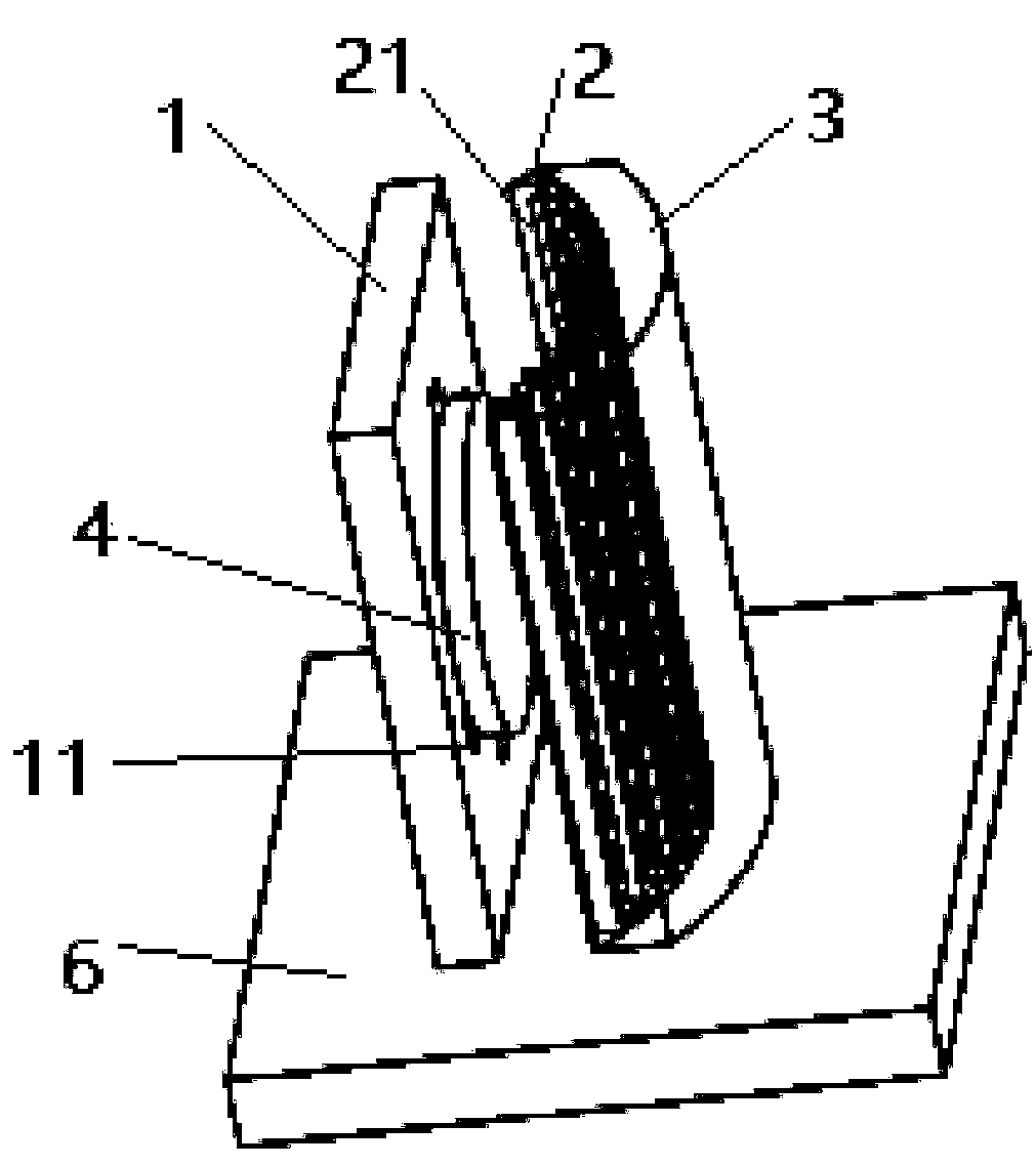
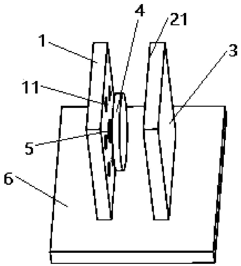
[0029] According to a specific embodiment of the present disclosure, an oil-gas separation structure is provided, figure 1 with figure 2 An embodiment of the oil-gas separation structure is s...


PUM


Abstract

The invention relates to an oil-gas separating structure, an engine cylinder cover and an engine. The oil-gas separating structure comprises a pore plate (1) and a flow blocking structure, wherein gasinlet pores (11) used for the entry of crankcase blow-by gas into the oil-gas separating structure are formed in the pore plate (1); the flow blocking structure is provided with an oil-gas separatingsurface (21); the oil-gas separating surface (21) comprises an impact zone of oil drops in the crankcase blow-by gas; and the flow blocking structure is configured to ensure that the area of the impact zone can be inversely proportionally changed along with the flow rate of the crankcase blow-by gas which enters the oil-gas separating structure. Through the above technical scheme, the oil-gas separating structure provided by the invention is simple, and the stable oil-gas separating efficiency can be achieved.

Description

technical field [0001] The present disclosure relates to the field of engines, in particular to an oil-gas separation structure for engine crankcase blow-by gas and the engine. Background technique [0002] When the engine is working, part of the combustible mixture and combustion products will escape from the cylinder to the crankcase through the piston ring, forming crankcase blow-by gas. Since the unburned fuel gas, water vapor and exhaust gas contained in the blow-by gas will dilute the oil, reduce the performance of the oil, and accelerate the oxidation and deterioration of the oil, therefore, it is necessary to separate the oil and gas from the blow-by gas to prevent oil droplets from entering The intake system produces carbon deposits, which in turn affects engine performance. [0003] Existing engines are usually equipped with an oil-gas separation structure to separate crankcase blow-by gas. Traditional oil-gas separation structures mainly include labyrinth baffle ...

Claims


Application Information

Patent Timeline
Patent Type & Authority Applications(China)
IPC IPC(8): F01M13/04
CPCF01M13/04F01M2013/0438
Inventor 曹康张旭邓厚劲
Owner BEIQI FOTON MOTOR CO LTD
Why Eureka
Try Eureka