A kind of hydrocyclone with cone slit structure

A technology of hydrocyclones and cones, which is applied in the direction of swirling devices and devices in which the axial direction of the swirling flow can be reversed, etc., which can solve the problems of increased pressure drop, large pressure drop, and high energy consumption

Active Publication Date: 2021-03-19
QINGDAO INST OF BIOENERGY & BIOPROCESS TECH CHINESE ACADEMY OF SCI +1
View PDF6 Cites 0 Cited by
  • Summary
  • Abstract
  • Description
  • Claims
  • Application Information

AI Technical Summary

Problems solved by technology

The traditional conventional hydrocyclone has a "one column and one cone" structure. Generally, the pressure drop of the fluid passing through the cyclone is controlled below 0.3MPa during operation. It is more common to operate the hydrocyclone near the pressure drop of 0.1MPa , if the pressure drop is too large, it will be difficult for general industrial pumps to provide their inlet pressure
Especially for small-sized hydrocyclones with high separation capacity, the pressure drop will increase sharply when the processing capacity is large, resulting in huge power consumption of the pump
Large pressure drop and high energy consumption have become one of the main factors restricting the processing capacity and application range of hydrocyclones

Method used


Image

  • A kind of hydrocyclone with cone slit structure
  • A kind of hydrocyclone with cone slit structure
  • A kind of hydrocyclone with cone slit structure

Examples


Embodiment 1

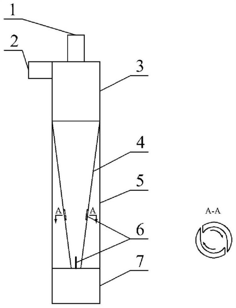
[0016] In this embodiment, the feed pipe 2 of the hydrocyclone and the cylindrical section 3 are self-contained, the overflow pipe 1 and the cylindrical section 3, the cylindrical section 3 and the conical section 4 and the casing 5, the casing 5 and the underflow pipe 7 are all Connection by flange. The cylindrical section 3 is 70mm high and 50mm in diameter, and the conical section 4 is 380mm high. Two symmetrical slits with an interval of 180° are opened at the bottom and the middle of the cone section 4 respectively, with a length of 40mm and a width of 3mm.

[0017] The liquid-solid mixture to be separated is transported to the feed pipe 2 through the slurry pump, and then enters the cylindrical section 3 of the hydrocyclone horizontally and tangentially to form a swirling flow. Due to the density difference of the liquid-solid mixture, under the action of centrifugal force, the solid particles are thrown to the side wall as a heavy phase, and make a spiral motion downwa...

Embodiment 2

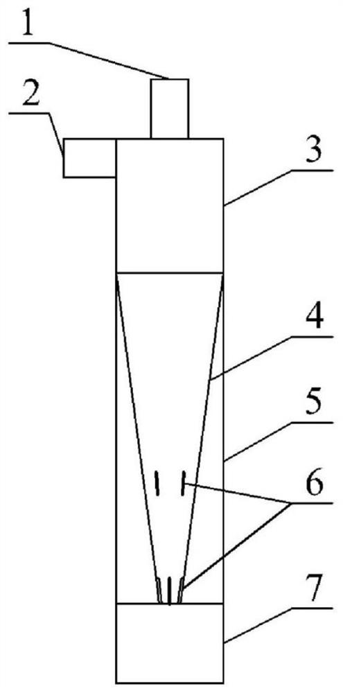
[0023] In this embodiment, the feed pipe 2 of the hydrocyclone and the cylindrical section 3 are self-contained, the overflow pipe 1 and the cylindrical section 3, the cylindrical section 3 and the conical section 4 and the casing 5, the casing 5 and the underflow pipe 7 are all Connection by flange. The cylindrical section 3 is 70mm high and 50mm in diameter, and the conical section 4 is 380mm high. Four symmetrical slits with an interval of 90° are opened at the bottom and the middle of the cone section 4 respectively, the length is 20mm, the width is 1mm, and the lower end of the middle slit is 120mm from the bottom of the cone section 4.

[0024] The liquid-solid mixture to be separated is transported to the feed pipe 2 through the slurry pump, and then enters the cylindrical section 3 of the hydrocyclone horizontally and tangentially to form a swirling flow. Due to the density difference of the liquid-solid mixture, under the action of centrifugal force, the solid partic...


PUM


Abstract

The invention discloses a hydrocyclone for a cone slit structure. The hydrocyclone comprises a material feed tube, a cylinder section, a cone section, a sleeve, an overflow tube, and a bottom flow tube, wherein slits are formed in the middle lower position of the wall of the cone section, the slits are distributed uniformly and circumferentially with a central axis of the cone as a center line, the bottom of the cone section is sealed, and a separated heavy phase slides from the cone section to the sleeve in a slit tangential direction and is discharged by the bottom flow tube. Compared with aconventional hydrocyclone of the same size, the hydrocyclone with the cone tangential slit structure maintains high separation efficiency of the conventional hydrocyclone, greatly lowers pressure drop, and can be applied to occasions requiring high energy consumption, such as internal process strengthening of a slurry bed reactor.

Description

technical field [0001] The invention relates to the technical field of liquid-solid separation, in particular to a hydrocyclone with a cone-shaped slot structure. Background technique [0002] Hydrocyclones are often used in the field of solid-liquid separation. The basic principle is the same as that of a centrifuge, so that the suspended particles in the solid-liquid two phases are separated from the liquid under the action of centrifugal acceleration. It is widely used because of its simple structure, low equipment cost, small footprint and large processing capacity. [0003] Pressure drop is an important technical index and operation index of hydrocyclone. The pressure drop of hydrocyclone should be as small as possible to reduce energy consumption. The traditional conventional hydrocyclone has a "one column and one cone" structure. Generally, the pressure drop of the fluid passing through the cyclone is controlled below 0.3MPa during operation. It is more common to op...

Claims


Application Information

Patent Timeline
Patent Type & Authority Patents(China)
IPC IPC(8): B04C5/081
CPCB04C5/081
Inventor 黄青山肖航陈阿强杨超
Owner QINGDAO INST OF BIOENERGY & BIOPROCESS TECH CHINESE ACADEMY OF SCI
Why Eureka
Try Eureka