Tensile force stroke compensating device

A stroke compensation and tension technology, which is applied in the field of tension stroke compensation devices, can solve the problems that the cylinder shrinkage sling does not reach the maximum bearing capacity and the deformation is large, and achieves the effects of compact structure, convenient operation and good work flexibility.

Active Publication Date: 2018-11-02
SPECIAL EQUIP SAFETY SUPERVISION INSPECTION INST OF JIANGSU PROVINCE
View PDF26 Cites 1 Cited by
  • Summary
  • Abstract
  • Description
  • Claims
  • Application Information

AI Technical Summary

Problems solved by technology

For slings with large elastic deformation such as cotton ropes, nylon ropes, and fiber ropes, the amount of deformation is large, and the slings do not reach the maximum carrying capacity even if the oil cylinder is fully contracted.

Method used


Image

  • Tensile force stroke compensating device
  • Tensile force stroke compensating device
  • Tensile force stroke compensating device

Examples


Embodiment Construction

[0031] The specific implementation manner of the present invention will be described below in conjunction with the accompanying drawings.

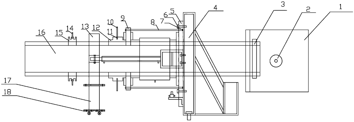
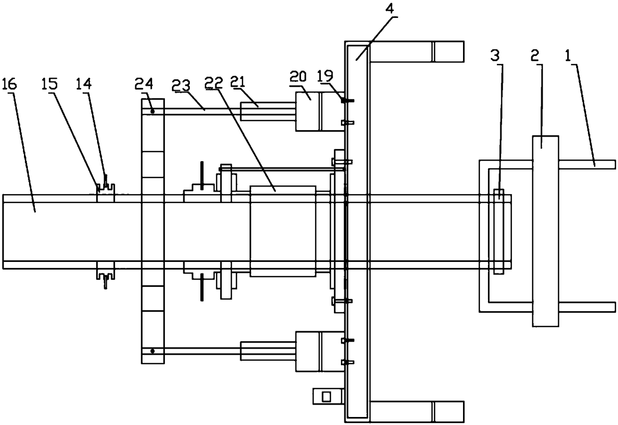
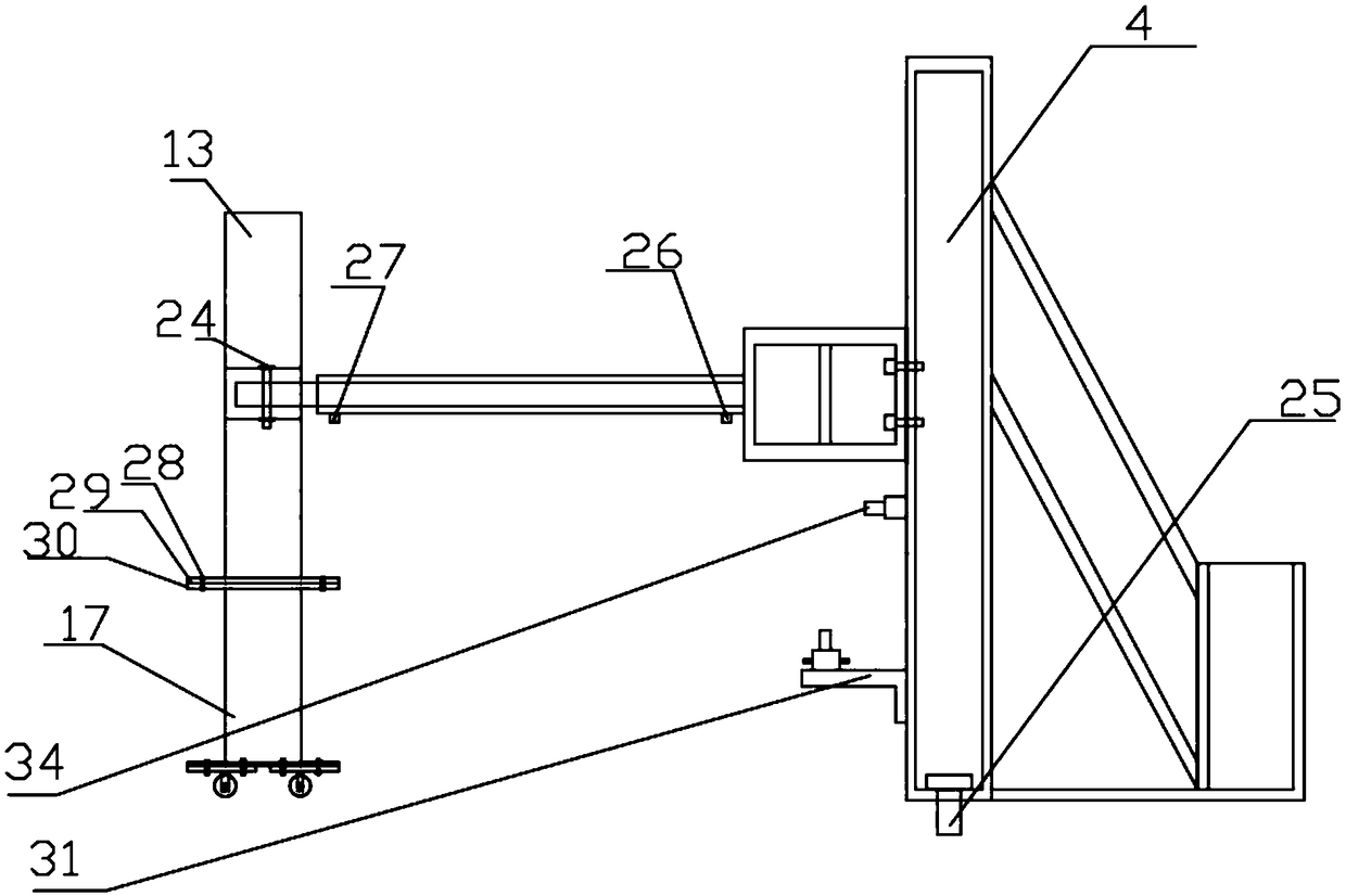
[0032] Such as Figure 1-Figure 5 As shown, the tension stroke compensation device of this embodiment includes a tension frame 4, the middle part of the tension frame 4 passes through the tension screw 16, the head of the tension screw 16 is threaded to the slider 1, and the slider 1 is passed through the lock nut 3 and the first pin shaft 2 are fixed; the end face of the tensile frame 4 is equipped with a support flange 5 through the first fixing bolt 6, and a flange support 9 is arranged at an interval from the support flange 5, and the flange support 9 is installed on the tension screw 16 There are multiple screws 8 connected between the support flange 5 and the flange support 9, and the screws 8 are fixed by the nut 7; one side of the flange support 9 is close to the pressure sensor 22, and the other side is used as a thread retaining ...


PUM


Abstract

A tensile force stroke compensating device comprises an anti-tensile frame, wherein the middle part passes through a tensile screw; the head part of the tensile screw is connected with a puller through thread; the puller is fixed with a locking nut and a first pin shaft; the end face of the anti-tensile frame is provided with supporting flanges through first fixing bolts, flange supports are arranged at the interval between the supporting flanges, the flange supports are arranged outside the tensile screw, a plurality of screws are connected between the supporting flanges and the flange supports, and the screws are fixed with nuts; one side of the flange supports abut against a pressure sensor, and the other side of the flange supports are used as a stop block of a thread stop ring, the thread stop ring sleeves outside the tensile screw, a handle screw hole is arranged on the thread stop ring, a manual handle is arranged in the handle screw hole, an end stop ring is also arranged on the outer ring of the tensile screw rod, a rotating handle is arranged on the end stop ring; the device also comprises a running mechanism, wherein trolley supporting legs are arranged on the running mechanism; and a hydraulic telescopic mechanism is arranged between the trolley supporting legs and the anti-tensile frame. The working is reliable.

Description

technical field [0001] The invention relates to the technical field of compensation devices, in particular to a tension stroke compensation device. Background technique [0002] At present, the tension machine mainly includes subsidence type and open type. The subsidence tensile machine is located in the concrete pit, and the tensile machine is constructed by concrete, with a simple structure, but the length, width, and height of the concrete pit are fixed, and the size of the tested construction is limited. The open tensile machine is located on the ground, and the tension is carried by longitudinal beams and beams. The structure is complex. Generally, the width of the construction can exceed the width of the tensile machine. Some tensile machines have adjustable axial spacing, which greatly adapts to the test of large-scale construction. [0003] The loading method of most tensile machines is hydraulic loading. The tensile testing machine is generally divided into two pa...

Claims


Application Information

Patent Timeline
Patent Type & Authority Applications(China)
IPC IPC(8): F15B15/22G01N3/08
CPCF15B15/221G01N3/08
Inventor 王松雷邓宏康
Owner SPECIAL EQUIP SAFETY SUPERVISION INSPECTION INST OF JIANGSU PROVINCE
Why Eureka
Try Eureka