
Direct air-cooling system for optimization of flow distribution of steam

A steam flow and optimized distribution technology, which is applied to steam/steam condensers, lighting and heating equipment, etc., can solve the problems of uneven distribution of steam flow, uneven temperature of condensed water, and incomplete cooling of places with high flow of tube bundles. Achieve the effects of reducing the stress asymmetry of the tube bundle, improving the thermal load matching ability, and improving the antifreeze summer ability

Inactive Publication Date: 2018-11-02
DATANG GANSU POWER GENERATION
View PDF0 Cites 2 Cited by
  • Summary
  • Abstract
  • Description
  • Claims
  • Application Information

AI Technical Summary

Problems solved by technology

The diameter of the steam distribution pipe gradually decreases from 3m to 1m, and the size of the finned tube bundle is 200×20mm. The distribution of steam flow between different tube bundles is uneven. In summer and winter, the current air-cooled power plant adopts the operation mode of grouping and stopping the fans, so the steam with low flow rate of the tube bundles will be overcooled, and the place with high flow rate of the tube bundles cannot be completely cooled, resulting in High back pressure, easy to freeze in winter
Moreover, the cross wind has a great influence on it. When the cross wind comes, the air intake of the unit near the cross wind is small, and the air intake of the leeward side is relatively large, which will easily lead to uneven temperature of the condensate in each unit, and the condensate of the unit on the windward side. The temperature is too high, the amount of condensed water is too small, and the temperature of condensed water on the leeward side is too low, etc.

Method used


Image

  • Direct air-cooling system for optimization of flow distribution of steam
  • Direct air-cooling system for optimization of flow distribution of steam
  • Direct air-cooling system for optimization of flow distribution of steam

Examples


Embodiment Construction

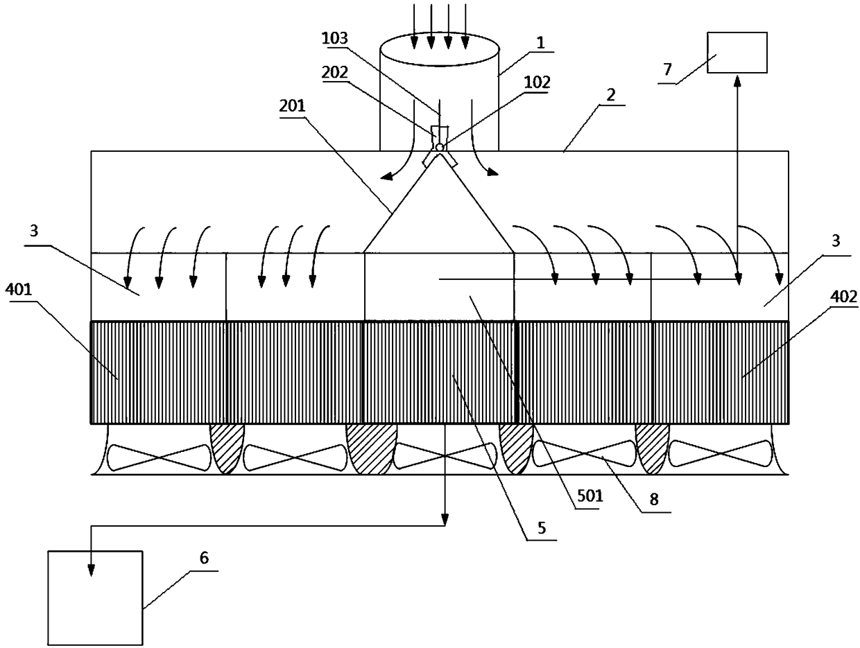
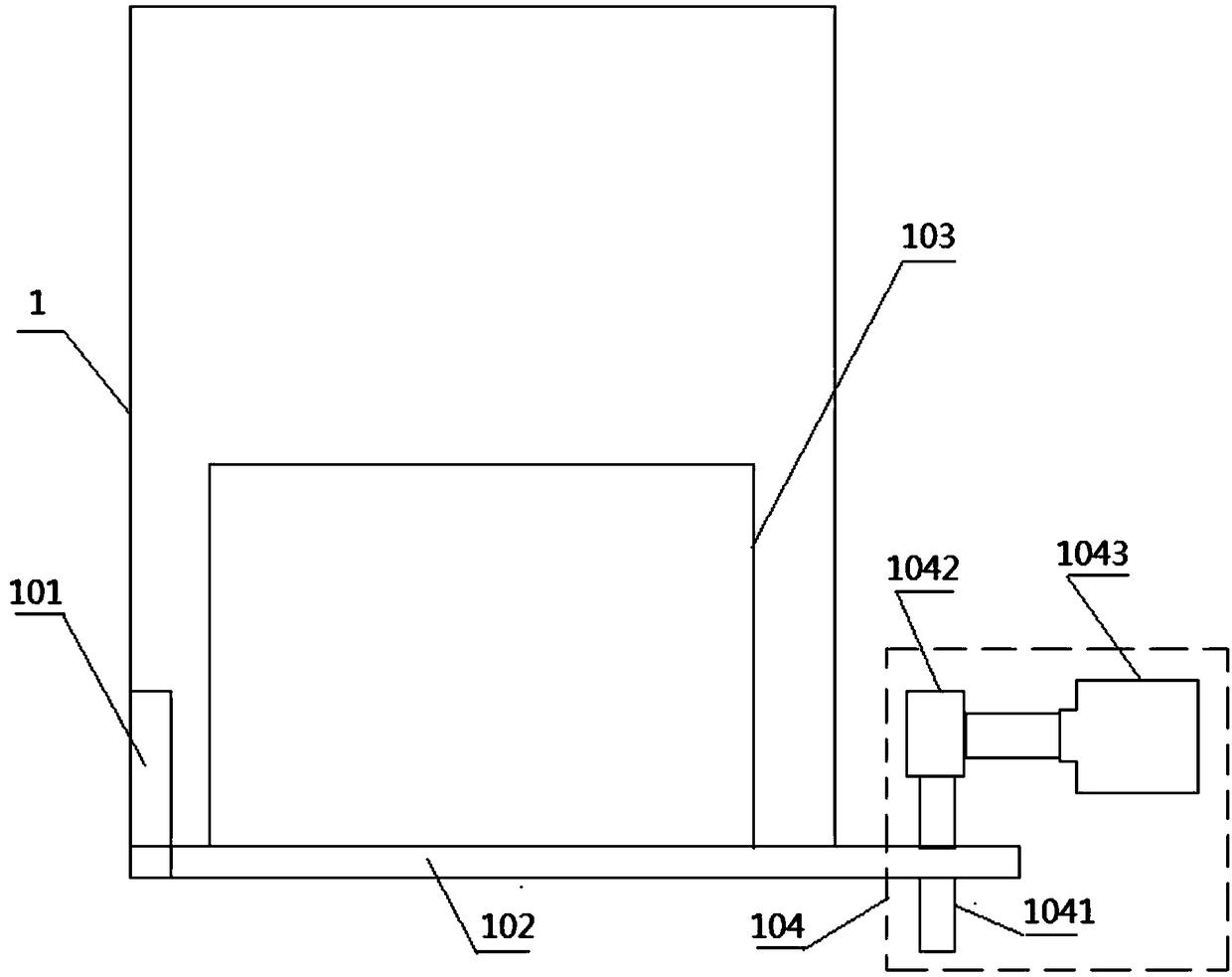
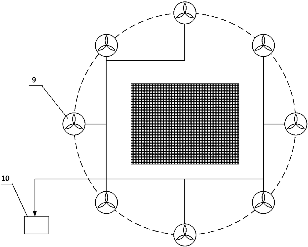
[0030] refer to figure 1 and figure 2 , the direct air cooling system for optimizing the distribution of steam flow in the present invention includes a vertically arranged steam introduction pipe 1, the lower end of the steam introduction pipe 1 is connected with a horizontally arranged steam distribution pipe 2, and the lower end of the steam distribution pipe 2 is connected with a plurality of buffer covers 3 , a plurality of buffer covers 3 are symmetrically arranged at both ends of the steam distribution pipe 2; the lower end of each buffer cover 3 is correspondingly connected with a set of tube bundles 4 in the downstream area; multiple sets of tube bundles 4 in the downstream area include a windward side tube bundle 401 and a leeward side tube bundle 402 , a tube bundle 5 in the upstream side tube bundle 401 and a tube bundle 402 on the leeward side is provided in the middle; a steam header 501 is connected to the upper end of the tube bundle 5 in the countercurrent zon...


PUM


Abstract

The invention discloses a direct air-cooling system for optimization of flow distribution of steam. The system comprises a vertically-arranged steam introducing pipe. The lower end of the steam introducing pipe communicates with a horizontally-arranged steam distributing pipe. The lower end of the steam distributing pipe communicates with multiple buffer covers. The lower end of each buffer covercorrespondingly communicates with a group of forward-flow area pipe bundles. Each forward-flow area pipe bundle comprises a windward-side pipe bundle and a leeward-side pipe bundle. An adverse flow area pipe bundle is arranged in the middle between each windward-side pipe bundle and each leeward-side pipe bundle. A flow guide board is arranged in the steam introducing pipe and swing leftwards andrightwards in the steam introducing pipe. An inverted-V-shaped baffle board is arranged in the steam distributing pipe. According to the actual demand, distribution of steam flow in the steam distributing pipe is adjusted such that steam-side thermal load matches air-side air quantity. Therefore, the heat exchange capability of the system is increased. Meanwhile, distribution of steam flow is controlled according to wind speed and wind direction of the environment. Therefore, optimization and matching of thermal load in the air-cooling system is realized. Therefore, an anti-freezing and over-summer capability of the system is enhanced.

Description

technical field [0001] The invention belongs to the technical field of cooling systems of thermal power plants, and in particular relates to a direct air cooling system for optimally distributing steam flow. Background technique [0002] Due to my country's rich coal and water shortage, the development of thermal power generation in the northern region is greatly constrained by water resources. In recent years, the development of air-cooled units has made the northern region break through the constraints of water resources, and gradually produced a number of high-parameter, large-capacity power plants. direct and indirect air cooling units. The technology of direct air-cooled units is relatively mature, but due to the low heat transfer coefficient of the air and the fact that the direct air-cooled condenser is directly in contact with the air, it is greatly affected by the environment, especially sensitive to cross winds, and may even cause direct cross winds in summer. Blow...

Claims


Application Information

Patent Timeline
IPC IPC(8): F28B1/06F28B9/00
CPCF28B1/06F28B9/00
Inventor 李江海乔万谋薛守武李世虎徐松泉贺鹏张兴荣杨博武海德
Owner DATANG GANSU POWER GENERATION
Learn More