Solar panel display screen
A technology of solar panels and solar panels, applied in the direction of electric vehicles, instruments, electrical components, etc., can solve problems such as difficult cleaning, achieve the effects of convenient installation and disassembly, flexible cost control, and increase display density
- Summary
- Abstract
- Description
- Claims
- Application Information
AI Technical Summary
Problems solved by technology
Method used
Image

Examples
Embodiment 1
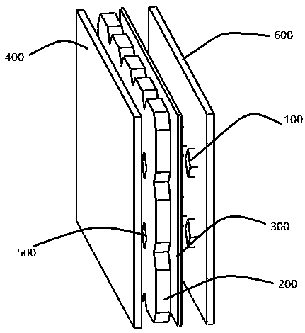
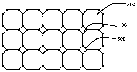
[0020] Embodiment 1: as figure 1 In this embodiment, the system includes: a lamp bead 100, a solar panel 200, and a back panel 300, which are characterized in that several solar panels 200 are laminated into a whole through the front panel 400 and the back panel 300; Adjacent solar cell panels 200 are tightly spliced side by side, and there are lamp beads 100 in gaps between the chamfered corners 500 of adjacent solar cell panels 200 .
[0021] The lamp bead 100 is on the PCB substrate 600, the gap formed by the chamfer on the solar panel corresponds to the position of the lamp bead on the substrate, the edge of the lamp bead 100 corresponds to the hypotenuse of the chamfer 500, and the material of the back plate 300 is transparent , there is a groove on the back panel 300 for fitting with the lamp bead 100, so that the lamp bead 100 can be inserted into the chamfer gap between the solar panels 200 through the back panel 300, realizing an ultra-thin design, and the light is...
Embodiment 2
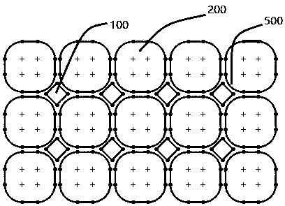
[0022] Embodiment 2: In this embodiment, the system is as in Example 1 figure 1 In the same way, several solar panels 200 are integrated into a whole through the lamination of the front panel 400 and the back panel 300; in this embodiment 2, as image 3 There are rounded corners 500 at the junction of the middle solar panel 200 ; there are lamp beads 100 at the rounded corners 500 .
[0023] Each lamp bead 100 is installed independently without a common PCB substrate. The light bead 100 is controlled by a wireless module (not shown in the figure), and the lamp bead 100 is powered by a wire connection. It is more suitable for chamfering or rounding corners of large-pitch solar panels and large lamp beads.
[0024] In practice, the most preferred 5050 patch lamp bead is 45 degrees from the horizontal, and the chamfer or fillet or trimming of the solar panel is adjusted according to the length and width of the lamp bead. For example, when the 3528 lamp bead is used, the chamfer ...
PUM
 Abstract
Description
Claims
Application Information
 - R&D
- Intellectual Property
- Life Sciences
- Materials
- Tech Scout
- Unparalleled Data Quality
- Higher Quality Content
- 60% Fewer Hallucinations
Browse by: Latest US Patents, China's latest patents, Technical Efficacy Thesaurus, Application Domain, Technology Topic, Popular Technical Reports.
© 2025 PatSnap. All rights reserved.Legal|Privacy policy|Modern Slavery Act Transparency Statement|Sitemap|About US| Contact US: help@patsnap.com