
Electric equipment and power control device and method thereof

A technology for power control and electrical equipment, which is applied to output power conversion devices, circuit devices, battery circuit devices, etc., and can solve the problem of increased volume and weight of portable high-power electrical equipment, increased cost and safety management pressure, and difficulty in outputting large output. power and other issues, to achieve the effect of enhancing practicability, enhancing the scope of application, and improving output power

Pending Publication Date: 2018-11-02
SUZHOU LUCK POWER ELECTRONICS TECH CO LTD
View PDF0 Cites 1 Cited by
  • Summary
  • Abstract
  • Description
  • Claims
  • Application Information

AI Technical Summary

Problems solved by technology

Therefore, even when there is access to the power grid or a range extender, it is difficult for existing portable high-power electrical equipment to output greater power, thus limiting its scope of application
Although the output power of portable high-power electrical equipment can be increased by increasing the power of lithium battery packs, the number of lithium batteries will increase, which will increase the volume and weight of portable high-power electrical equipment. thereby reducing portability
In addition, pressure on cost and safety management of lithium batteries will also increase

Method used


Image

  • Electric equipment and power control device and method thereof
  • Electric equipment and power control device and method thereof
  • Electric equipment and power control device and method thereof

Examples


Embodiment Construction

[0071] In order to enable those skilled in the art to better understand the technical solutions in the present application, the technical solutions in the embodiments of the present application will be clearly and completely described below in conjunction with the drawings in the embodiments of the present application. Obviously, the described The embodiments are only some of the embodiments of the present application, but not all of them. Based on the embodiments in this application, all other embodiments obtained by persons of ordinary skill in the art without creative efforts shall fall within the scope of protection of this application.

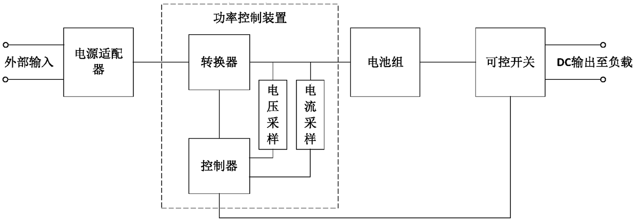
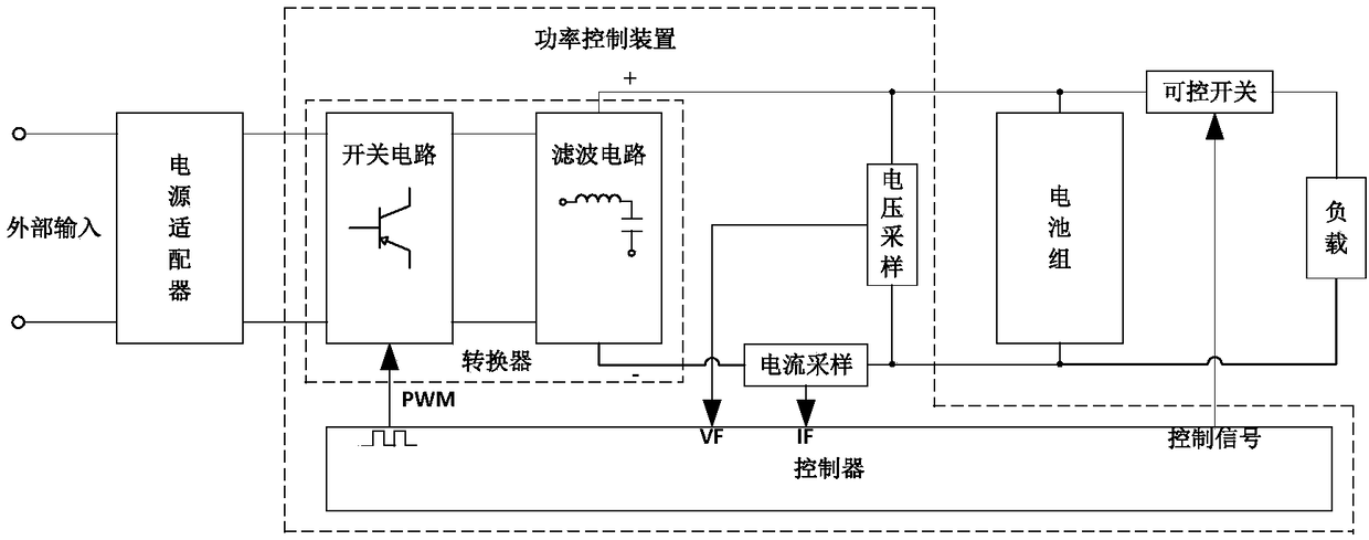
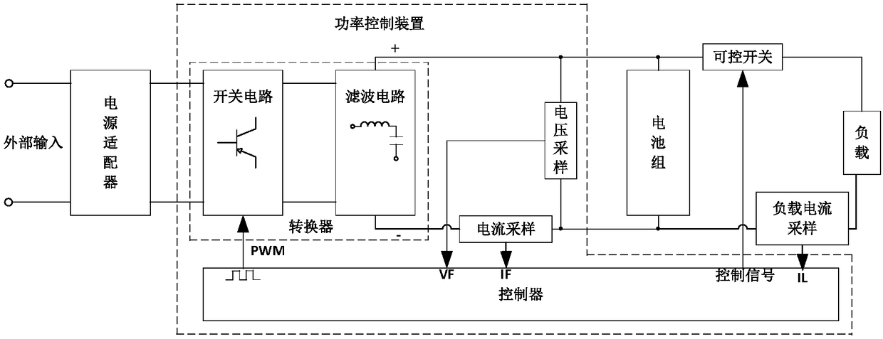
[0072] refer to figure 1 As shown, the electric device in the embodiment of the present application may include a power adapter, a power control device coupled with the power adapter, a battery pack coupled with the power control device, and the like. Wherein, the power control device may include a converter, a voltage sampling circuit, ...


PUM


Abstract

The embodiment of the invention provides electric equipment and a power control device and method thereof. The power control device comprises a converter, a voltage sampling circuit, a current sampling circuit and a controller, wherein the input end of the converter is coupled with the output end of a power adapter of the electric equipment so as to convert the output of the power adapter into direct current with constant power; the input end of the voltage sampling circuit is coupled with the output end of the converter so as to collect the output voltage of the converter; the input end of the current sampling circuit is coupled with the output end of the converter so as to collect the output current of the converter; and the input end of the controller is coupled with the output end of the voltage sampling circuit and the output end of the current sampling circuit so as to control the converter to maintain constant-power output according to the output voltage and the output current,so that the converter is connected in parallel with a battery pack of the electric equipment in a constant power mode to supply electricity. According to the embodiment of the invention, the portability of the electric equipment is considered while the application range of the electric equipment is enlarged, so that the application range of the electric equipment is expanded.

Description

technical field [0001] The present application relates to the technical field of power control of portable high-power electrical equipment, in particular to an electrical equipment, a power control device and a power control method thereof. Background technique [0002] Portable high-power electrical equipment (such as welding machines, cutting machines, etc.) is often used in scenarios such as high-altitude operations, field operations, and emergency relief. In order to adapt to the above scenarios, generally these portable high-power electrical devices are integrated with battery packs to meet the application when there is no access to the grid. Considering its portability, application scenarios and cost, the battery packs of these high-power electric devices often have limited battery life. [0003] In order to prolong the endurance of the battery pack of high-power electrical equipment, it is also possible to charge the battery pack of high-power electrical equipment th...

Claims


Application Information

Patent Timeline
Patent Type & Authority Applications(China)
IPC IPC(8): H02J7/34H02M3/156
CPCH02J7/34H02M3/156
Inventor 佟天野
Owner SUZHOU LUCK POWER ELECTRONICS TECH CO LTD
Learn More