

Excitation device and excitation-free working brake
A technology of excitation devices and brakes, which is applied in the direction of electric brakes/clutches, electromechanical devices, electric components, etc., can solve problems such as difficulties in the development of electromagnetic coupling devices, and achieve simple manufacturing, ensure coil space, and simple manufacturing
- Summary
- Abstract
- Description
- Claims
- Application Information
AI Technical Summary
Problems solved by technology
Method used
Image

Examples
no. 1 approach
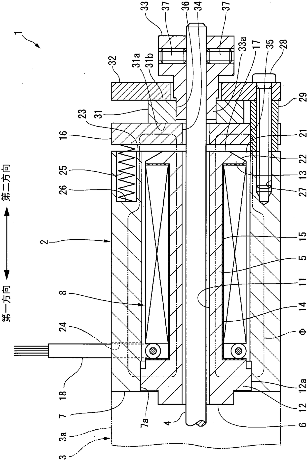
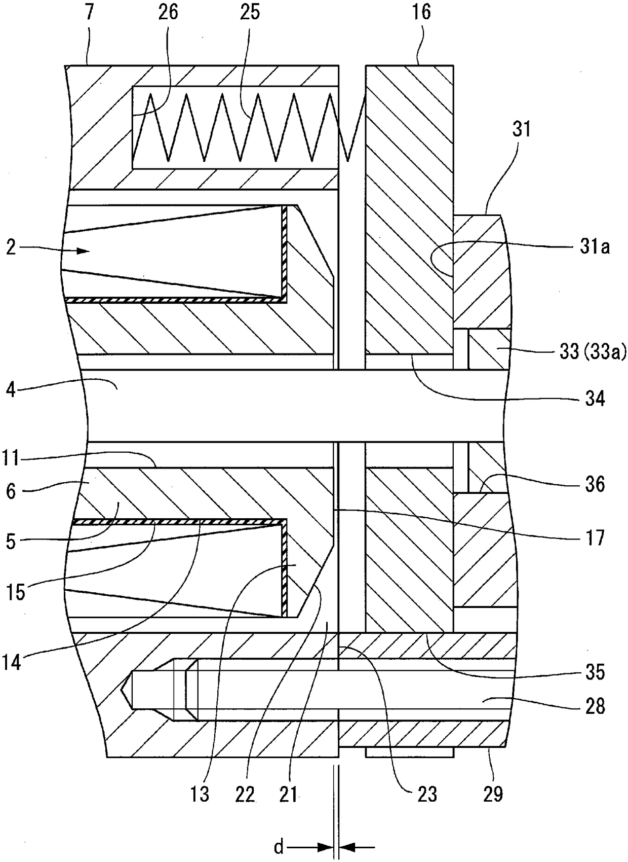
[0025] As follows, while referring to figure 1 and figure 2 , while describing in detail the field device and the non-excitation service brake according to the first embodiment of the present invention.
[0026] figure 1 The non-excited working brake 1 shown uses the excitation device 2 to operate, in figure 1 The end portion on the left side is attached to the rear case 3 a of the servo motor 3 . Hereinafter, the direction in which the rear shell 3a is located with respect to the non-excitation working brake 1 (in figure 1 The left side in the middle) is called "first direction", and the direction opposite to this direction is called "second direction". In addition, when there are two members, the member located in the first direction is named "one (member)", and the member located in the second direction is named "another (member)". Fill in the name of the component in "(component)".
[0027] The rear case 3 a rotatably supports the motor shaft 4 of the servo motor 3 ...
no. 2 approach
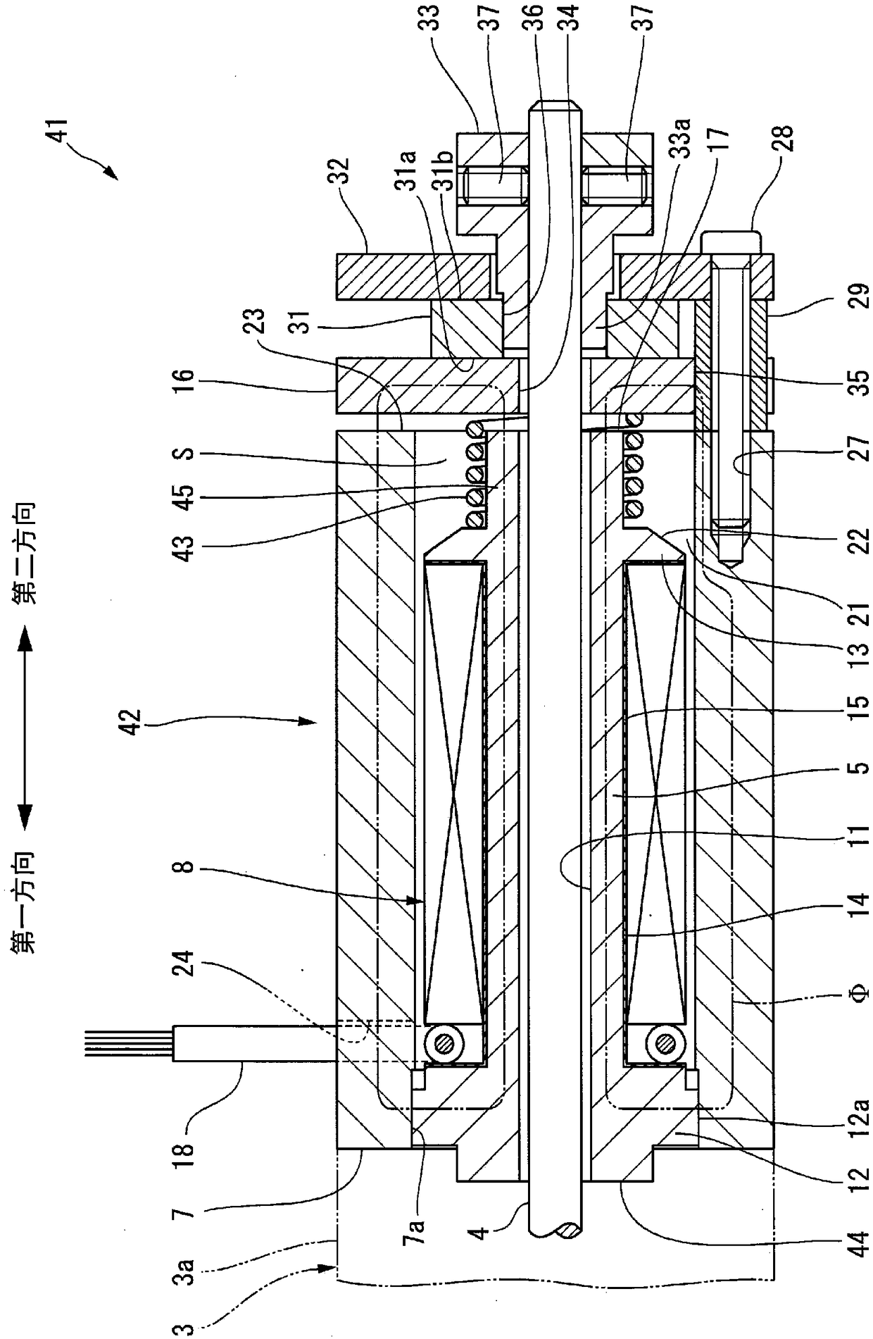
[0055] Next, refer to image 3 , the excitation device and the non-excitation service brake according to the second embodiment of the present invention will be described. exist image 3 in, against and use figure 1 and figure 2 Members that are the same as or equivalent to those described will be given the same reference numerals, and detailed descriptions will be appropriately omitted. image 3 The de-energized working brake 41 shown with figure 1 The non-excitation working brake 1 shown is only different in a part of the excitation device 42 and the brake spring 43, and the other structures are the same.
[0056] The inner pole member 44 of the exciting device 42 has an extending portion 45 extending from the second flange portion 13 toward the armature 16 . The extended portion 45 is formed in a cylindrical shape having an outer diameter smaller than the outer diameter of the front end surface (the surface on the armature 16 side) of the second flange portion 13 . In...
no. 3 approach
[0062] Next, refer to Figure 4 , the excitation device and the non-excitation service brake according to the third embodiment of the present invention will be described. exist Figure 4 in, against and use figure 1 and figure 2 Members that are the same as or equivalent to those described will be given the same reference numerals, and detailed descriptions will be appropriately omitted. Figure 4 The de-energized working brake 51 shown with figure 1 The non-excitation working brake 1 shown is only different in a part of the excitation device 52 and the brake spring 53, and the other structures are the same.
[0063] Figure 4The inner pole component 54 of the illustrated exciter device 52 has an extension 55 extending from the second flange part 13 towards the armature 16 . The extended portion 55 in this embodiment is formed in a truncated cone shape whose outer diameter becomes smaller as the distance from the second flange portion 13 increases. The inner magnetic p...
PUM
 Abstract
Description
Claims
Application Information