
Indoor coverage system

An indoor coverage system and feeder technology, applied in the transmission system, electromagnetic wave transmission system, radio transmission system, etc., can solve the problems that users cannot effectively use mobile services, reduce the utilization rate of mobile network resources, and the output power of antenna ports is difficult to balance. Achieve the effect of improving wireless network resource utilization, improving network resource utilization, and improving communication coverage

Inactive Publication Date: 2018-11-02
河南京科科技有限公司
View PDF5 Cites 14 Cited by
  • Summary
  • Abstract
  • Description
  • Claims
  • Application Information

AI Technical Summary

Problems solved by technology

[0009] Due to the structure of the house and other reasons, the antenna is usually placed on the outer wall of the owner's door. The traditional coverage solution has a large feeder loss, and it is difficult to balance the output power of the antenna port, resulting in low power at the end antenna port, causing indoor coverage blind spots, and users cannot effectively use mobile phones. business
Reduce the utilization of mobile network resources and reduce user perception
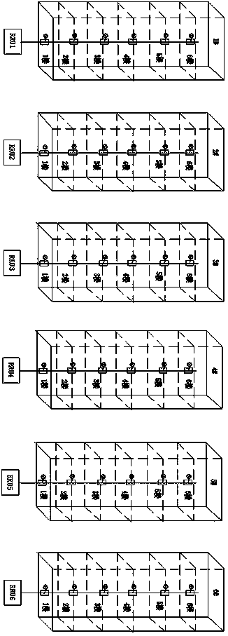
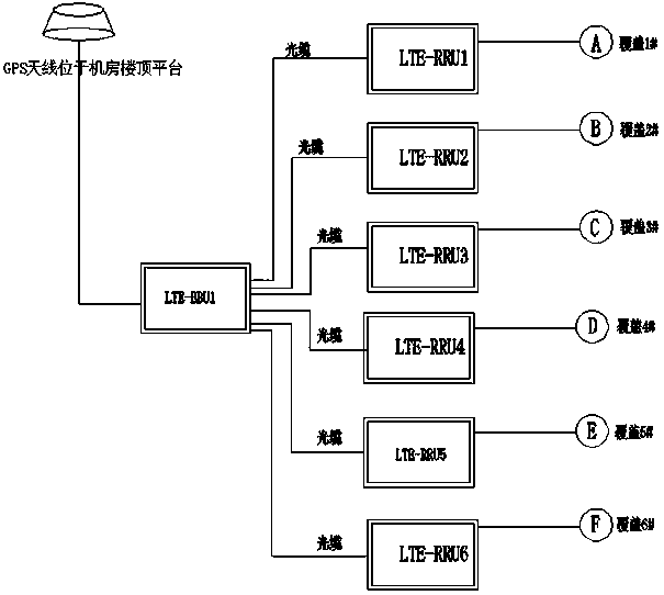
At the same time, if figure 1 , 2 As shown, many existing indoor coverage systems have been covered by RRU and BBU equipment, which improves the signal strength of the indoor mobile network. However, due to the large number of RRU and BBU equipment used, such as figure 1 , 2 Among them, 6 buildings use 6 RRU devices, and the cost of the large number of RRUs leads to high overall cost of networking in the community

Method used


Image

  • Indoor coverage system
  • Indoor coverage system
  • Indoor coverage system

Examples


Embodiment Construction

[0033] The technical solution of the indoor coverage system of the present invention will be further elaborated and described below in conjunction with the accompanying drawings and specific embodiments.

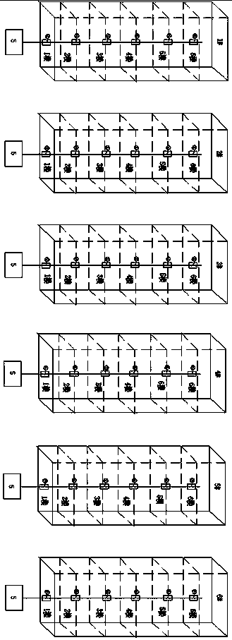
[0034] An indoor coverage system such as image 3 , 4 , 5, including baseband processing unit BBU, remote radio module RRU, near-end control unit, extension unit, remote access unit, power divider, coupler, feeder cable and antenna; The RRU is connected to the near-end control unit through an optical fiber, the near-end control unit is connected to the expansion unit through an optical cable, and the expansion unit is connected to the remote access unit through a photoelectric composite cable , the remote access unit is connected to indoor and outdoor antennas through feeders, couplers, and power dividers. The antenna includes an indoor plate antenna 8 and an outdoor spotlight antenna. The plate antenna is located on each floor of the indoor corridor and is close to the in...


PUM


Abstract

The invention provides an indoor coverage system. The system comprises a baseband backup unit (BBU), a radio remote unit (RRU), a proximal control unit, an expansion unit, a remote access unit, a power divider, a coupler, a feeder cable, a connector and an antenna, wherein the BBU is connected with the RRU through an optical fiber; the RRU is connected with the proximal control unit through an optical fiber; the proximal control unit is connected with the extension unit through an optical cable; the expansion unit is connected with the remote access unit through an optoelectronic composite cable; output ports of the power divider and the coupler are connected with the feeder cable; the feeder cable is laid indoors and outdoors; an indoor antenna is fixed to the feeder cable and close to anindoor user; and an outdoor antenna is fixed to a roof and outdoor wall. Thus, a wireless network forms best coverage indoors; an indoor user can absorb more traffics; and the utilization rate of wireless network resources is increased.

Description

technical field [0001] The invention belongs to the technical field of wireless communication, and in particular relates to a novel indoor and outdoor coverage system. Background technique [0002] Indoor mobile accounts for about 70% of the entire mobile network business. Indoor signal quality has become a key factor for operators to gain a competitive advantage. As an effective supplementary coverage for outdoor macro stations, the indoor distribution system is aimed at indoor user groups and mainly solves problems in buildings. The network coverage of the mobile communication network, the scheme of network capacity and network quality, and the distribution design of the indoor antenna feeder system are one of the main factors affecting the quality of indoor communication. Therefore, the design of the indoor coverage scheme is very important to improve network performance. [0003] In traditional room distribution system antenna design, it is usually chosen to install a di...

Claims


Application Information

Patent Timeline
IPC IPC(8): H04W16/20H04W16/26H04B10/2575H04W88/08H04B7/26
CPCH04B7/2609H04B10/25754H04W16/20H04W16/26H04W88/085
Inventor 张国兴
Owner 河南京科科技有限公司
Learn More