

Liquid material feeding system and working method
A liquid feed and conveying system technology, applied in the field of livestock and poultry breeding, can solve the problems of inconvenient configuration of liquid feed, heavy maintenance, and cumbersome construction, and achieve the effects of easy fine management, labor cost saving, and easy observation and comparison
- Summary
- Abstract
- Description
- Claims
- Application Information
AI Technical Summary
Problems solved by technology
Method used
Image

Examples
Embodiment 1
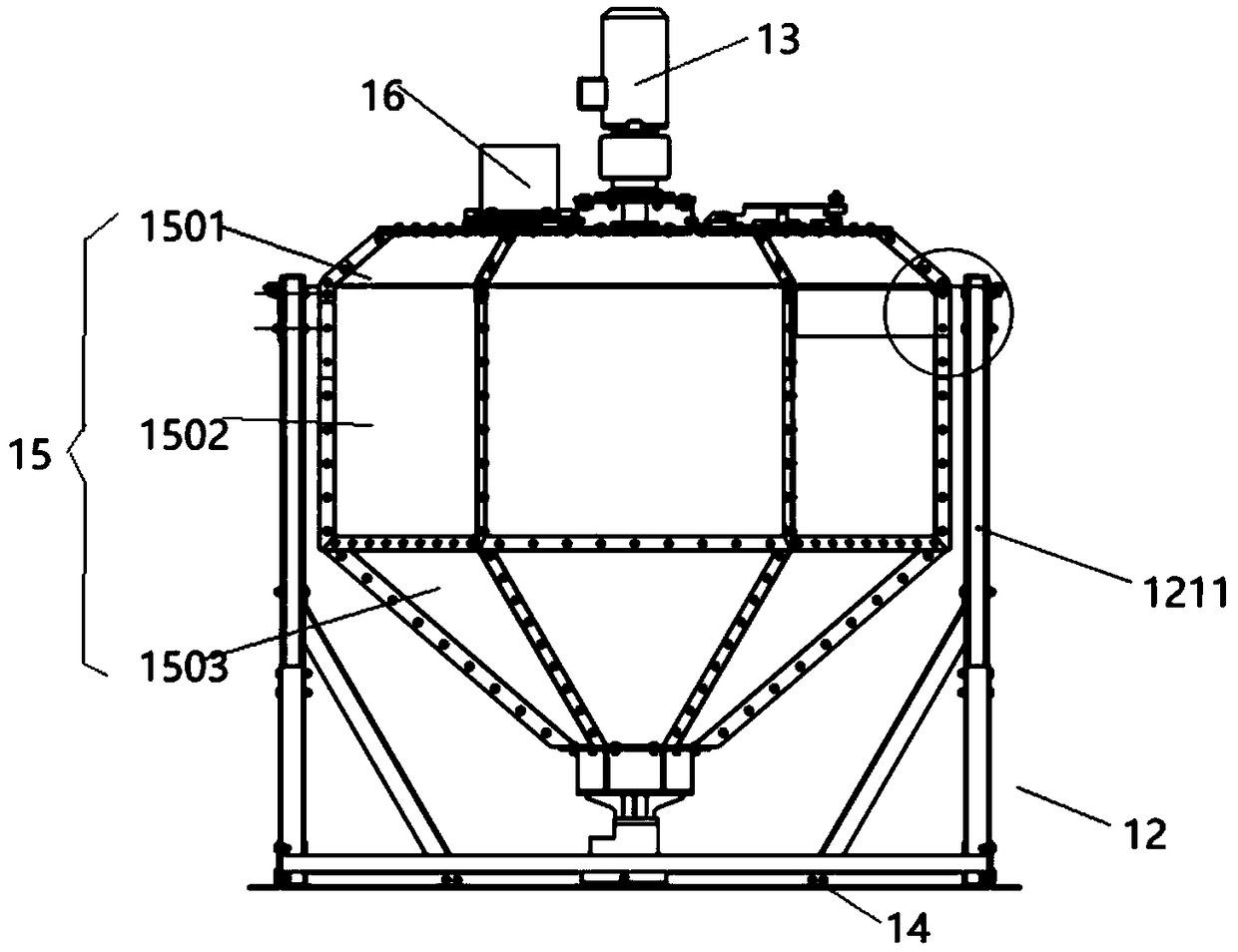
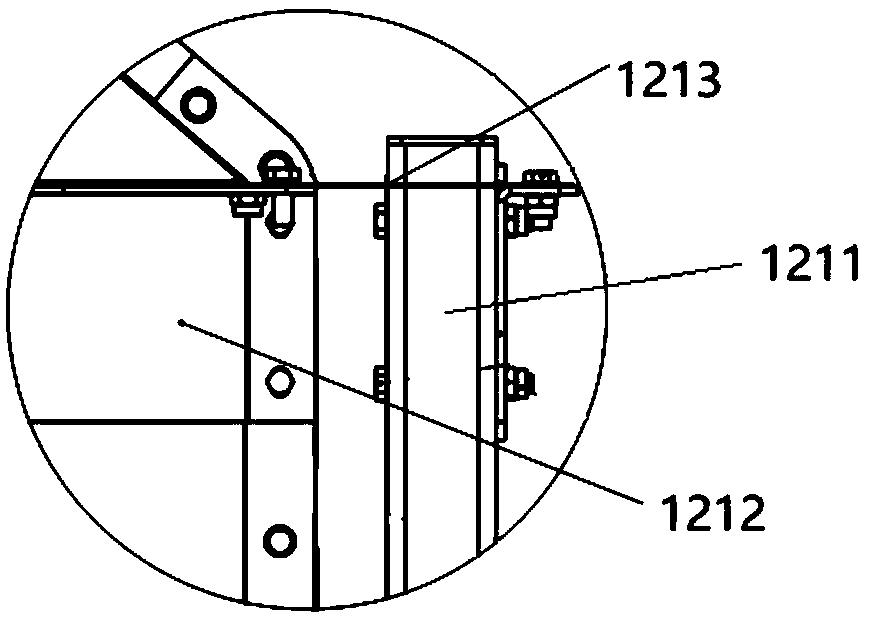
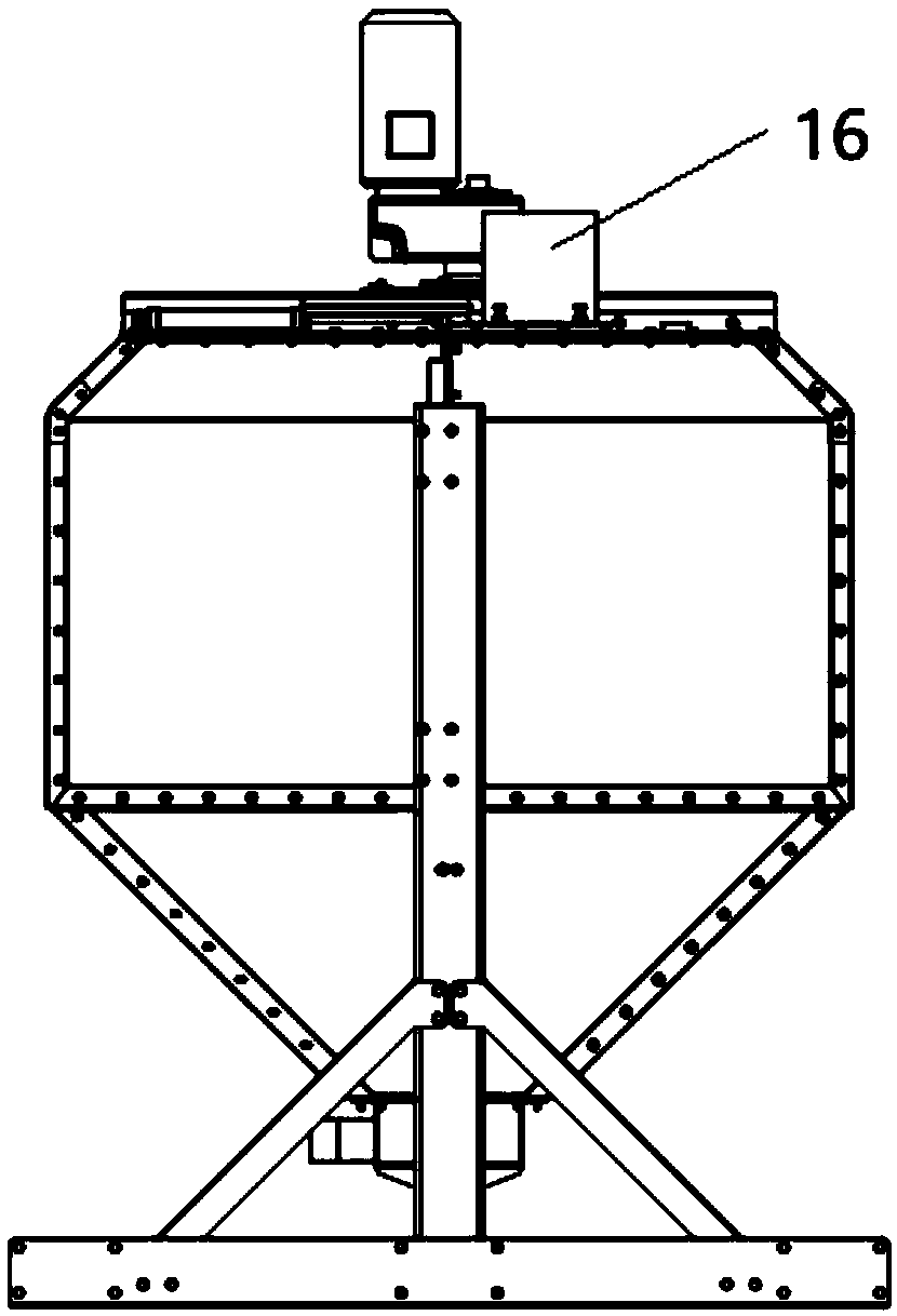
[0055] Such as Figure 1-8 Shown, a kind of liquid material feeding system comprises stirring device 4, conveying system and control system, and described stirring device 4 comprises mixing cylinder 15 and is used for fixing the mixing cylinder support 12 of this mixing cylinder 15, and opening on this cylinder body The cross section is a regular hexagonal structure, and the cylinder body includes an upper end 1501, a middle end 1502 and a lower end 1503, the upper end 1501 and the lower end 1503 are conical structures, and the mixing cylinder bracket includes a bracket column 1211 A connecting steel plate 1212 is provided above the middle end portion 1502 of the cylinder block, the connecting steel plate 1212 is fixed with a limiting plate 1213 by bolts, and the other end of the limiting plate 1213 is fixed with the support column 1211 by means of bolts, Since the liquid material is weighed by fluid, the weighing stability is the biggest difficulty, so the connection between ...
Embodiment 2
[0066] This embodiment is further optimized on the basis of Embodiment 1. Specifically, the cover plate is provided with an observation cover 17, and the observation cover 17 and the cover plate 23 are fixed by locking buckles 1701, which is convenient for staff to patrol. Observe the agitation in the tank during inspection.
Embodiment 3
[0068]This embodiment is further optimized on the basis of Embodiment 1. Specifically, the paddle stirring mechanism 18 includes a main shaft, blades 1802 and positioning rods 1804. The main shaft is connected to the stirring reduction motor 13, and the connection is provided with protection sleeve 1801, the lower end of the main shaft is fixedly connected with a second rotary joint 1803, one end of the positioning rod 1804 is fixed to the protective sleeve 1801, and the other end is fixed to the side wall of the second rotary joint 1803, the setting of the positioning rod 1804 is In order to avoid damage to the main shaft after long-term use and prolong the life of the paddle stirring mechanism 18, the main shaft and positioning rod 1804 can be made of telescopic rods, which can adjust the paddle stirring mechanism and the liquid level according to the liquid level of the liquid material in the cylinder. The depth of contact makes the mixing more uniform.
PUM
 Abstract
Description
Claims
Application Information