Wind guiding type mosquito killing lamp easy to clean

A wind-driven, mosquito-killing lamp technology, which is applied to the device, application, and animal husbandry of capturing or killing insects, can solve the problems of affecting the killing effect, deviation of mosquitoes, and inability to kill effectively, so as to improve the efficiency of killing insects. The effect of killing rate and improving the killing effect

Inactive Publication Date: 2018-11-06
徐志华
View PDF5 Cites 3 Cited by
  • Summary
  • Abstract
  • Description
  • Claims
  • Application Information

AI Technical Summary

Problems solved by technology

[0003] At present, the commonly used methods of killing mosquitoes are mainly divided into drug fumigation, spraying liquid medicine, electric mosquito lamps, etc., and using electric mosquito lamps is the most environmentally friendly and harmless way. When electric mosquito lamps are used to kill mosquitoes, Using the phototaxis of insects, the lamp tube is used to attract mosquitoes, but due to the heat of the lamp tube, the mosquitoes may deviate when they approach, so that they cannot be effectively killed, and they may escape autonomously after entering the electric mosquito lamp, thus Affect killing effect

Method used


Image

  • Wind guiding type mosquito killing lamp easy to clean
  • Wind guiding type mosquito killing lamp easy to clean
  • Wind guiding type mosquito killing lamp easy to clean

Examples


Embodiment 1

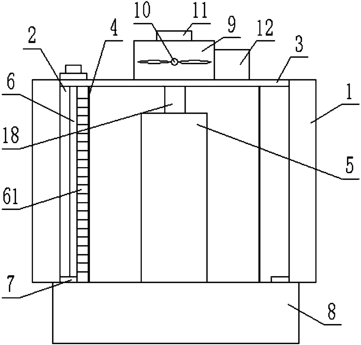
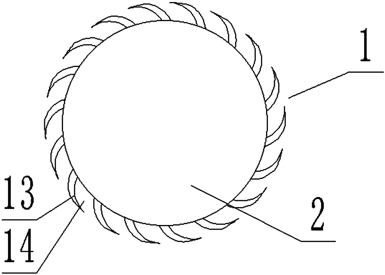
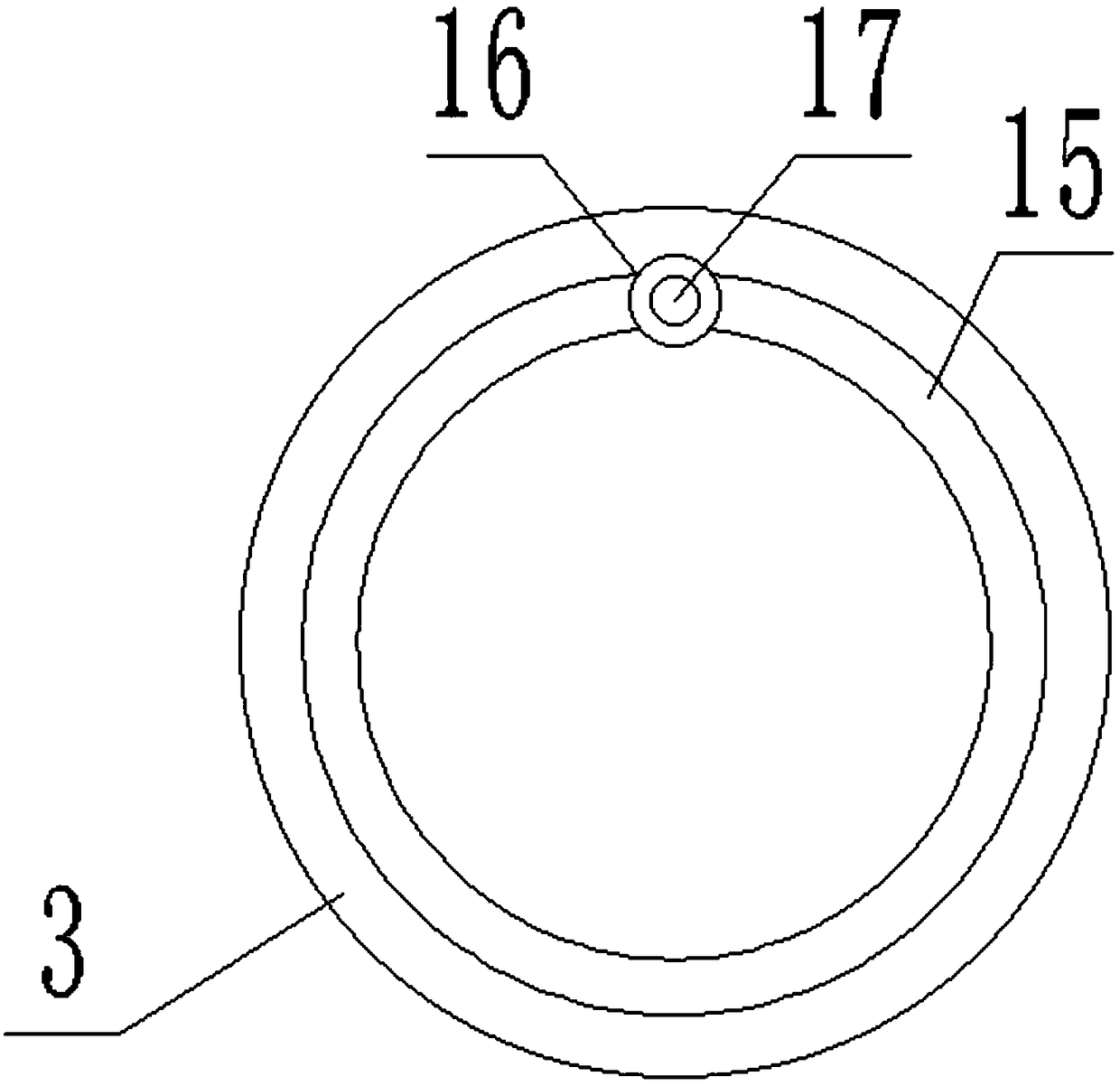
[0022] see Figure 1-3 , an easy-to-clean air-guided mosquito killer lamp, comprising an outer shell 1, an inner shell 2, a top cover 3, a motor net cover 4 to lure lights 5 and a collection box 8, the inner shell 2 is cylindrical and is located inside the outer shell 1, The lure lamp 5 is located at the center of the inner bottom surface of the inner shell 2, the motor grill 4 is cylindrical and is located between the inner wall of the inner shell 2 and the lure light 5, and a fan box 9 and a power supply box 12 are arranged above the inner shell 2. The bottom of the fan box 9 communicates with the inside of the inner shell 2, the fan box 9 is provided with an induced draft fan 10, the power supply box 12 is equipped with a power supply and the power supply is connected to the lure lamp 5, the motor net cover 4 and the induced draft fan 10 through wires respectively The shell 1 is composed of a plurality of arc-shaped glass plates 13 arranged at equal intervals along the circ...

Embodiment 2

[0028] The difference from Embodiment 1 is that the bottom of the fan box 9 is connected with a plurality of air ducts, and the air ducts extend downwards into the inner shell 2 and are located between the electric shock grille 4 and the lure lamp 5. A plurality of ventilation holes, through the arrangement of air ducts, make the airflow generated at different heights in the inner shell 2 uniform, so that mosquitoes can be sucked into the device faster and killed when they approach.


PUM


Abstract

The invention discloses a wind guiding type mosquito killing lamp easy to clean. The wind guiding type mosquito killing lamp easy to clean comprises an outer shell, an inner shell, a top cover, a motor net cover lure lamp and a collecting box, wherein the inner shell is cylindrical and is positioned on the inner side of the outer shell; the lure lamp is positioned in the center of the inner bottomsurface of the inner shell; the motor net cover is cylindrical and is positioned between the inner wall of the inner shell and the lure lamp; a fan box and a power supply box are arranged above the inner shell; the bottom of the fan box communicates with the inside of the inner shell; an induced draft fan is arranged in the fan box. By arrangement of the outer shell consisting of a plurality of arc-shaped glass plates, negative pressure is generated through the induced draft fan, when approaching the mosquito killing lamp, mosquitoes can be rapidly sucked into the mosquito killing lamp through air flow and then are killed, due to the effect of an arc-shaped glass plate, the circumstance that the mosquitoes escape after entering the mosquito killing lamp can be avoided, therefore, the mosquito killing rate is greatly increased, by arrangement of a sliding rod with a brush, the motor net cover is cleaned, and therefore, the mosquito killing effect of the device is improved.

Description

technical field [0001] The invention relates to mosquito killing equipment, in particular to an easy-to-clean air-guided mosquito killing lamp. Background technique [0002] Mosquitoes are inevitable disasters that affect human health when summer comes. They are one of the four pests. Blood-sucking female mosquitoes are intermediate hosts for other pathogens such as dengue fever, malaria, yellow fever, filariasis, and Japanese encephalitis. [0003] At present, the commonly used methods of killing mosquitoes are mainly divided into drug fumigation, spraying liquid medicine, electric mosquito lamps, etc., and using electric mosquito lamps is the most environmentally friendly and harmless way. When electric mosquito lamps are used to kill mosquitoes, Using the phototaxis of insects, the lamp tube is used to attract mosquitoes, but due to the heat of the lamp tube, the mosquitoes may deviate when they approach, so that they cannot be effectively killed, and they may escape auto...

Claims


Application Information

Patent Timeline
IPC IPC(8): A01M1/08A01M1/22
CPCA01M1/08A01M1/223
Inventor 徐志华
Owner 徐志华
Why Eureka
Try Eureka