Implant with bone absorption resistance

An implant and implantation technology, applied in the field of medical equipment, can solve the problems of poor firmness and sealing between the implant and the abutment, the contact area of ​​the taper + anti-rotation part is small, and the stress of the inner hole cannot be transmitted downward. Good initial stability, minimum self-tapping, and the effect of improving initial stability

Active Publication Date: 2018-11-06
JIANGSU TRAUSIM MEDICAL INSTR +1
View PDF6 Cites 4 Cited by
  • Summary
  • Abstract
  • Description
  • Claims
  • Application Information

AI Technical Summary

Problems solved by technology

[0002] The traditional implant uses Morse taper and multi-angle anti-rotation structure of the implant hole to complete the cooperation stability between the whole and the abutment. The common problem is that the taper + anti-rotation part has a small contact area, which will cause the occlusal force to fail to pass through the main body. It is evenly transmitted to the alveolar bone, thereby forming stress concentration in the implant neck, the firmness and sealing of the connection between the implant and the abutment are not good, and the abutment fretting and abutment-implantation are prone to occur under repeated loads Micro-gap between bodies, causing peri-implantitis
[0003] The initial stability of the single-head thread of the conventional implant is poor, there is no forward and reverse cutting groove, it is not easy to adjust the orientation, the inner hole is short, the stress cannot be transmitted downward, the stress concentration leads to fracture, the neck is tapered, and the cortical bone is squeezed. It is easy to cause bone resorption, the initial stability of the columnar shape is poor, and the flat and sharp design of the root end is poor in safety

Method used


Image

  • Implant with bone absorption resistance
  • Implant with bone absorption resistance
  • Implant with bone absorption resistance

Examples


Embodiment Construction

[0029] The preferred embodiments of the present invention will be described below with reference to the accompanying drawings. It should be understood that the embodiments described here are only used to illustrate and explain the present invention, and are not used to limit the present invention.

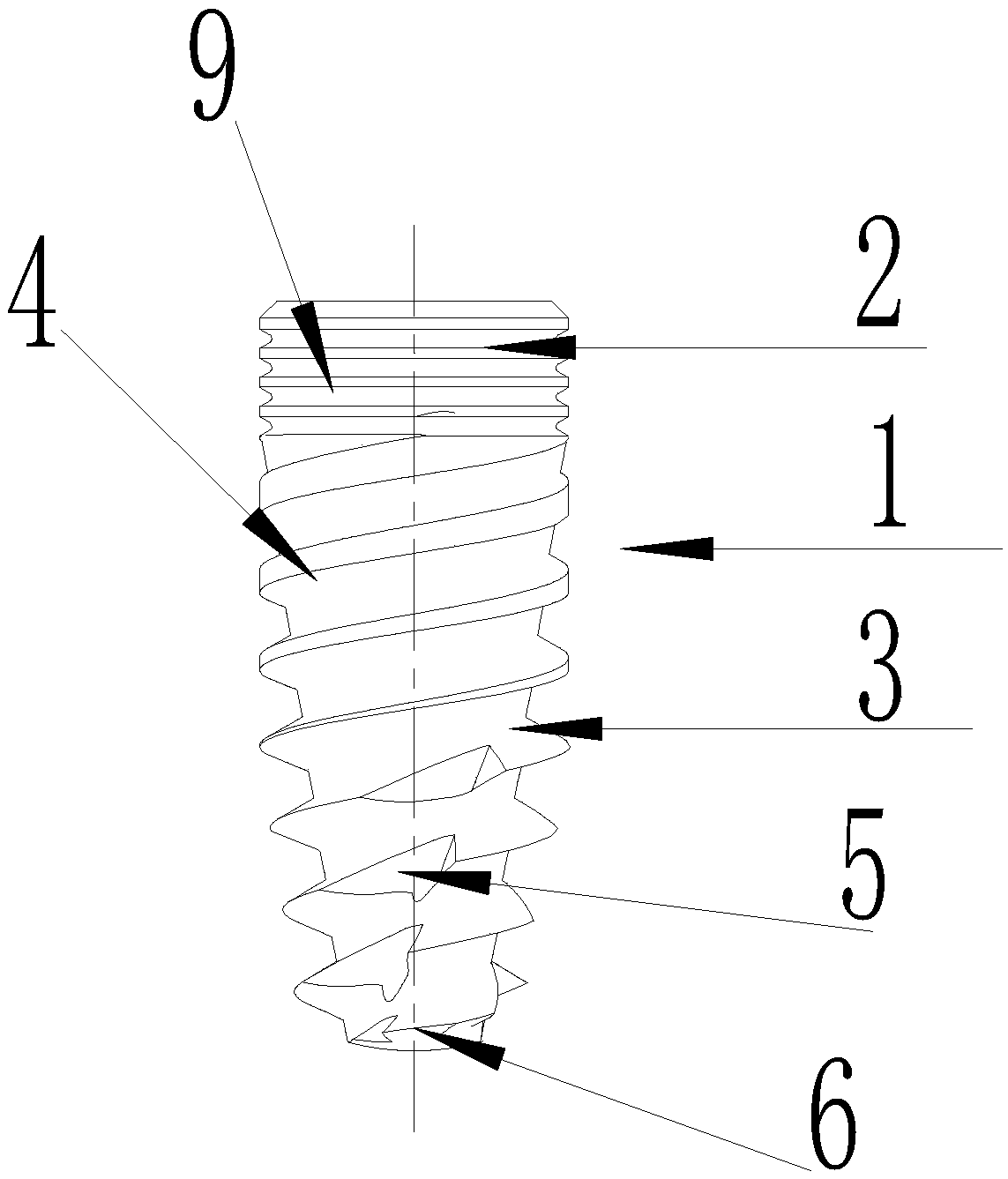
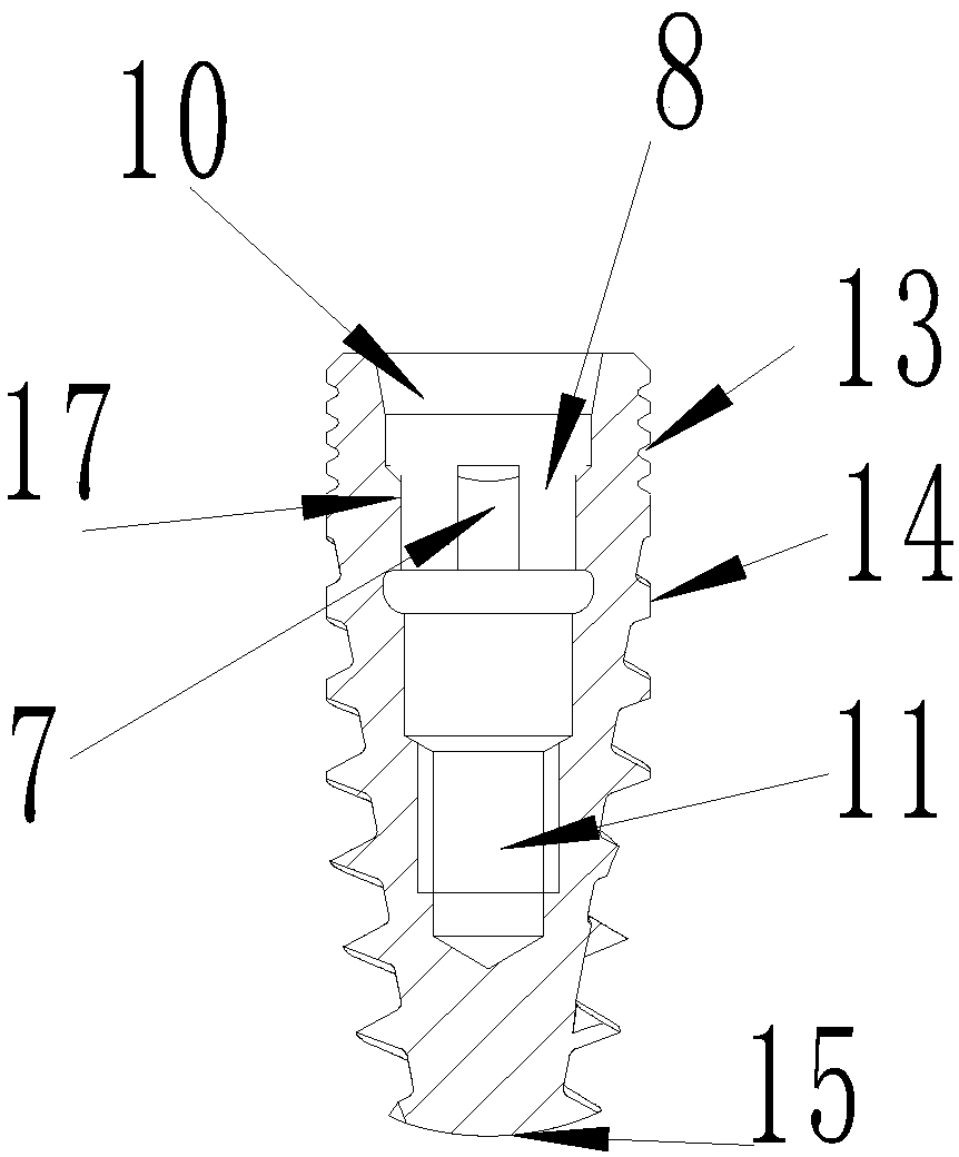
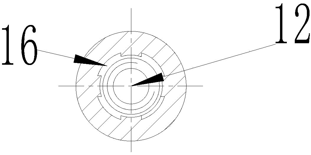
[0030] Such as Figure 1-Figure 3 As shown, an anti-bone resorption implant includes: a main body 1 and an implant hole 17, the implant hole 17 is opened inside the main body 1, wherein:

[0031] The shell of the main body 1 is a vertebral body structure, and the main body 1 is composed of a straight neck 2 and a vertebral body 3, and the straight neck 2 and the vertebral body 3 are integrally connected and formed. 3 is located below the straight neck 2, wherein the straight neck 2 is provided with a collar 9, the collar 9 is provided with a first thread 13, the surface of the vertebral body 3 is provided with a spiral structure 4, so The spiral structure 4 is provided with a second th...


PUM


Abstract

The invention discloses an implant with bone absorption resistance. The implant comprises a body and an implantation hole. The implantation hole is formed inside the body, a cone is positioned on thelower side of a straight neck, the straight neck is provided with a neck ring, the neck ring is provided with first threads, a spiral structure is arranged on a surface of the cone, second threads arearranged on the spiral structure, cutting grooves are formed in lower structures of the spiral structure, a root is arranged at the bottom of the cone, and a third thread is arranged on a surface ofthe root; the implantation hole comprises a first conical body implantation hole, a second conical body implantation hole, a padlock component hole and a fastening threaded hole which are sequentiallyformed in positions from the straight neck to the root, the padlock component hole is formed in four clamp teeth which are uniformly distributed, and a circular connector is arranged inside the clampteeth. The implant has the advantages that injury on surrounding tissues can be reduced, and stress concentration of the root and damage to bone tissues during implantation can be reduced.

Description

Technical field [0001] The present invention relates to the technical field of medical equipment, and more specifically to an anti-bone resorption implant. Background technique [0002] Traditional implants use Morse taper and the multi-angle anti-rotation structure of the implant hole to complete the stability of the fit between the whole and the abutment. The common problem is that the taper + anti-rotation part has a small contact area, which will cause the bite force to fail to pass through the main body. Evenly conduction to the alveolar bone, thus forming a stress concentration in the implant neck, the firmness and sealing of the connection between the implant and the abutment are not good, and the abutment fretting and abutment-implantation are prone to occur under repeated loads. Micro gaps between the bodies cause peri-implant inflammation. [0003] The initial stability of the single thread of conventional implants is poor, there is no forward and reverse cutting groove,...

Claims


Application Information

Patent Timeline
Patent Type & Authority Applications(China)
IPC IPC(8): A61C8/00
CPCA61C8/0018A61C8/0021A61C8/0025
Inventor 宿玉成钱晓锦
Owner JIANGSU TRAUSIM MEDICAL INSTR
Why Eureka
Try Eureka