
Self-coated non- vascular orifice insertion tube

A non-vascular, tube-inserting technology, applied in the field of rapid secondary coating devices, can solve the problems of long operation time, loss of drug properties, uneven thickness, etc., and achieve the effect of uniform coating and stable drug dosage

Inactive Publication Date: 2018-11-06
韩丽英
View PDF1 Cites 0 Cited by
  • Summary
  • Abstract
  • Description
  • Claims
  • Application Information

AI Technical Summary

Problems solved by technology

Because the lubricating oil required for the insertion of indwelling gastric tube or indwelling urinary catheter has fat-dissolving effect, the following defects are caused: ①The pre-lubricated cavity insertion tube widely used in existing hospitals, and the drug-coated insertion tube cannot be pre-lubricated operation, otherwise the activity is easily dissolved in lubricating oil, which is not conducive to local slow release; If it is long, it may cause the loss of the above medicinal properties
The use of this anesthetic drug also requires secondary treatment of the catheter during the operation, and during the treatment process, manual smearing, uneven thickness, and easy control of the drug dose

Method used

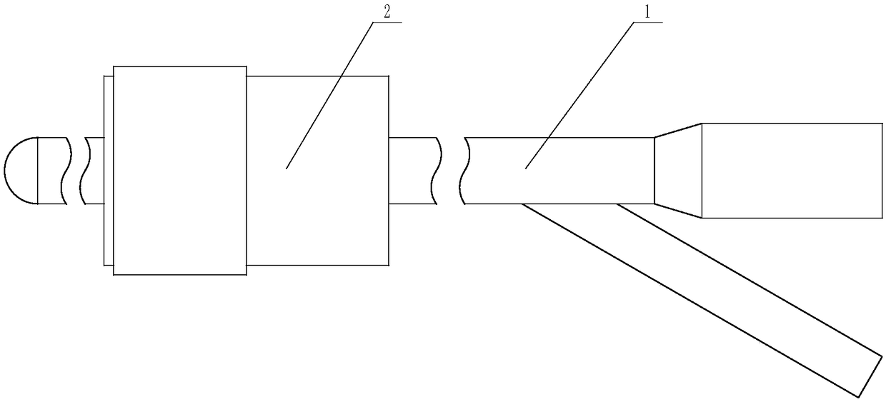
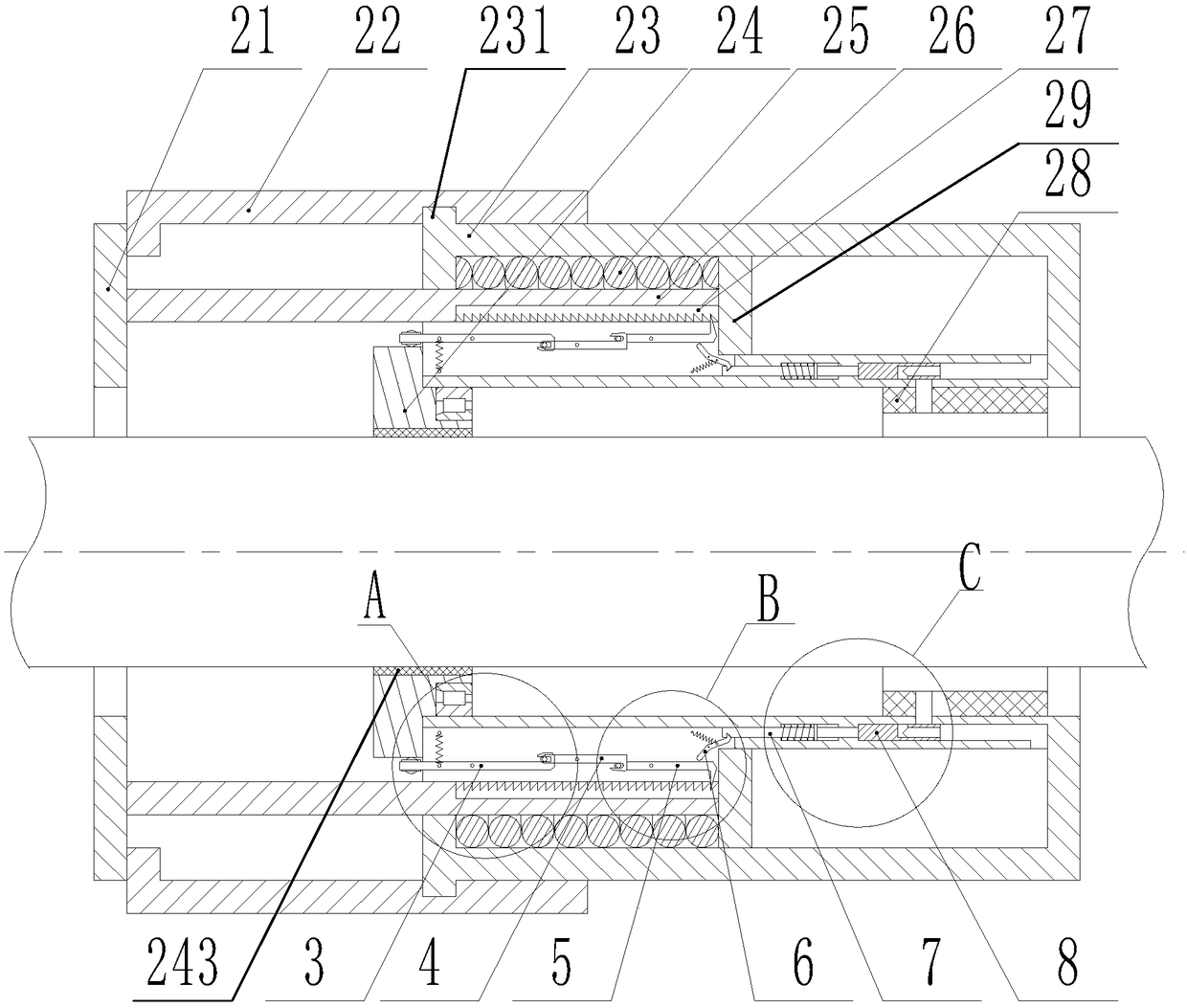
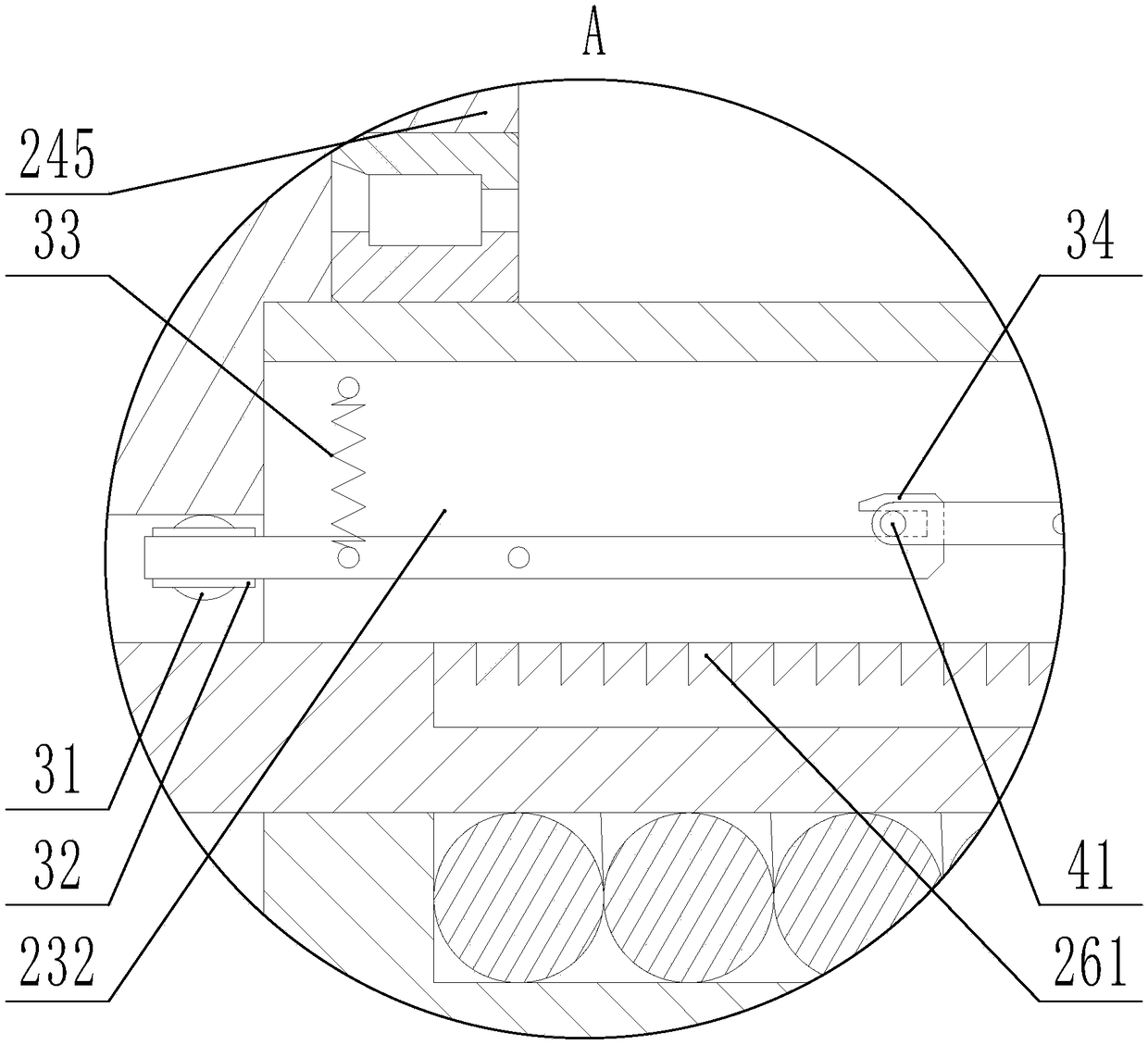

Image

  • Self-coated non- vascular orifice insertion tube
  • Self-coated non- vascular orifice insertion tube
  • Self-coated non- vascular orifice insertion tube

Examples


Embodiment 1

[0043] The outer cylinder 22 and the inner cylinder 23 described in Embodiment 1 are not fixed by a limiting device, so that the outer cylinder 22 is easily rotated relative to the inner cylinder 23 during transportation, so that the outer cylinder The arc-shaped stopper 221 at the left end of 22 rotates to the arc-shaped notch of the annular top plate 21, so that the ratchet 52 is subjected to excessive force, thereby causing damage. However, in embodiment 2, a limiting device is added to fix the outer cylinder 22 and the inner cylinder 23, as Figure 9 , 10 As shown, the inner wall of the right end of the outer cylinder 22 is provided with two symmetrically distributed notches 226, and a limit rod 222 is installed in the notch 226 of the outer cylinder, and the middle position of the limit rod 222 is Hinged with the side wall of the notch 226 of the outer cylinder 22, the outer wall of the inner cylinder 23 is provided with two positioning holes corresponding to the notch 2...


PUM


Abstract

The invention discloses a self-coated non-vascular orifice insertion tube, and belongs to the technical field of medical instruments. The self-coated non-vascular orifice insertion tube comprises a non-vascular orifice insertion tube, and is characterized in that the right end of an outer cylinder body sleeves the outer wall of the left end of an inner cylinder body, an annular piston is arrangedin an annular cavity of the inner cylinder body, the annular piston is connected with the right end of a sleeve, and the left end of the sleeve is connected with an annular top plate; a first compression spring is arranged between the annular piston and the left end wall of the inner cylinder body, the inner wall of the sleeve is provided with a plurality of fixing grooves, grooves corresponding to the fixing grooves are formed in the lower end wall of the annular cavity of the inner cylinder body, a ratchet bar is fixedly arranged in each fixing groove, the outer wall of a positioning wheel is provided with a plurality of arch-shaped protrusions arranged uniformly in a circumference, an arc-shaped groove is formed between every two arc-shaped projections, and the inner side end of a guiding ball abuts in an arc-shaped groove of the positioning wheel. Compared with the prior art, the self-coated non-vascular orifice insertion tube has the advantages of simple structure and reasonable design.

Description

technical field [0001] The invention relates to a medical device, in particular to a device capable of performing rapid secondary coating on a non-vascular lumen insertion tube. Background technique [0002] Non-vascular insertion tubes refer to tubes that are inserted into the human or animal body through the surface cavity and stay for a period of time, such as gastric tubes, urinary catheters, tracheal tubes, drainage tubes, etc. There are many types of cavity insertion tubes at present. Except for the direct incision or wound insertion of the drainage tube, other insertion tubes are inserted from the surface exposed cavity, such as gastric tube and endotracheal tube are inserted from the nasal cavity. [0003] During the insertion process, different insertion tubes have different configuration requirements. For example, nasogastric feeding tubes and urinary catheters only need basic lubrication, but if they need to be indwelled for a long time, in order to avoid local ir...

Claims


Application Information

Patent Timeline
Patent Type & Authority Applications(China)
IPC IPC(8): A61M25/00A61M16/04B05C1/06B05C11/10
CPCA61M25/0082A61M16/0402B05C1/06B05C11/10
Inventor 韩丽英王玉振
Owner 韩丽英
Learn More