Diaphragm coating device

A technology for coating devices and diaphragms, which is applied to devices and coatings for coating liquid on surfaces, can solve the problems of high initial investment in coating equipment, narrow coating thickness control range, and difficult post-maintenance, etc., and achieve production costs. Low cost, easy maintenance and cleaning, and the effect of reducing wear and tear

Inactive Publication Date: 2018-04-20
HEFEI XINGYUAN NEW ENERGY MATERIAL CO LTD
View PDF10 Cites 4 Cited by
  • Summary
  • Abstract
  • Description
  • Claims
  • Application Information

AI Technical Summary

Problems solved by technology

[0002] At present, diaphragm coating modification, as an effective means to enhance the thermal stability of the diaphragm and improve the adhesion between the diaphragm and the pole piece, has been effectively applied in the field of diaphragm manufacturing. Micro-gravure roller coating has good coating uniformity, The coating mechanism is simple and reliable, and the process repeatability is good. It is widely used. However, the coating of the micro concave roller is limited by its own structure. The micro concave roller and the scraper are seriously worn out. Considering the manufacturing cost, diaphragm coating manufacturers have tried New coating methods, among which two new coating methods, spray coating, extrusion + wire rod coating, have received more attention. Due to the limitations of some existing technologies, spray coating has not been widely used in the diaphragm field. Extrusion + wire rod coating The coating method has the advantages of fast coating speed and uniform coating, and has begun to be used in the field of diaphragm coating. However, the coating equipment has high initial investment, complicated equipment, difficult post-maintenance, and narrow coating thickness control range.

Method used


Image

  • Diaphragm coating device
  • Diaphragm coating device
  • Diaphragm coating device

Examples


Embodiment 1

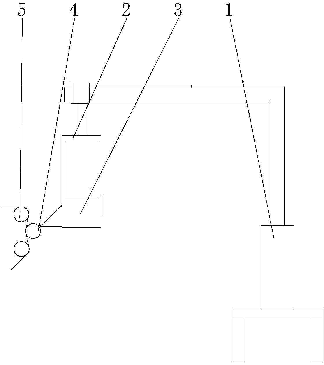
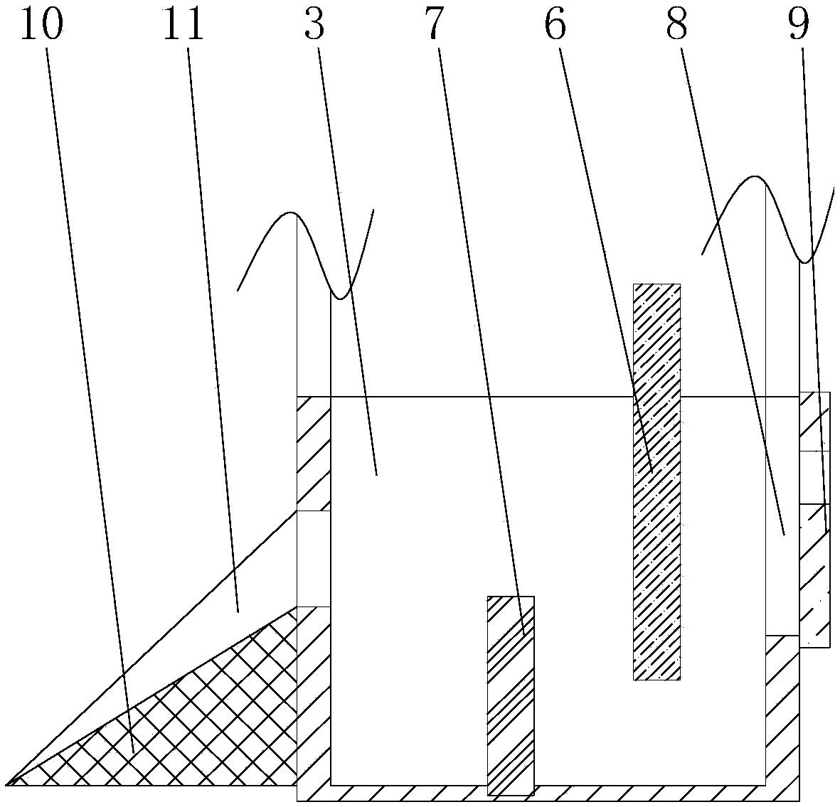
[0018] see Figure 1-2 , in an embodiment of the present invention, a diaphragm coating device includes a liquid storage tank 3 and an anilox roller 4 and a guide roller 5 arranged on the lower side of the liquid storage tank 3. The liquid storage tank 3 passes through the liquid storage tank hanger 2 and The support column 1 is fixed, the liquid storage tank 3 is arranged at the lower end of the liquid storage tank hanger 2, the liquid storage tank hanger 2 and the support seat 1 are slidably connected through guide rails, and the support seat 1 is provided with a hydraulic lifting rod, and the liquid storage tank 3 communicate with the slurry tank through the diaphragm pump and the pipeline, the liquid storage tank 3 is provided with a first stabilizing plate 6 and a second stabilizing plate 7, the first stabilizing plate 6 is fixedly connected with the liquid storage tank 3 and the second The bottom of the first stabilizing plate 6 is 1-5cm away from the bottom of the liqui...

Embodiment 2

[0022] Utilize the device of the present invention to carry out experiment and device structure is the same as embodiment 1.

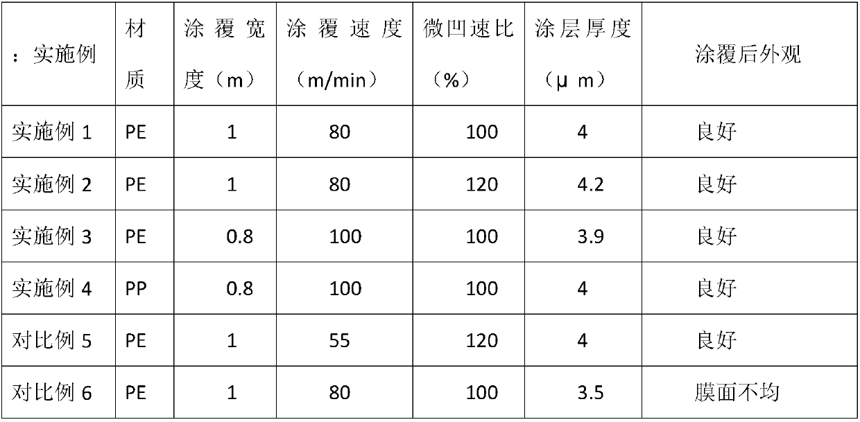
[0023] The coating width of the diaphragm is 1m, the speed ratio of dimples is 120%, the material is PE, and the coating speed is 80m / min. The performance of the diaphragm after coating is as follows;

Embodiment 3

[0025] Utilize the device of the present invention to carry out experiment and device structure is the same as embodiment 1.

[0026] This time, the diaphragm coating width is 0.8m, the dimple speed ratio is 100%, the material is PE, and the coating speed is 100m / min. The performance of the diaphragm after coating is as follows;


PUM


Abstract

The invention discloses a diaphragm coating device. The diaphragm coating device comprises a liquid storing groove, an anilox roller and a guide roller, wherein the anilox roller and the guide rollerare arranged at the lower side of the liquid storing groove; a slide plate is arranged at one side, close to the anilox roller, of the liquid storing groove; edge guide plates are arranged at two sides of the slide plate; an overflowing groove is formed in the rear side of the liquid storing groove; a liquid baffle plate is in slide connection with the liquid storing groove in the rear side of theoverflowing groove. The diaphragm coating device has the beneficial effects that a coating manner integrating slope current and a micro concave roller is performed, and a scraping knife is not used,so that the abrasion loss of the micro concave roller can be effectively decreased, and the coating can be quickly carried out; the device is simple in structure, low in manufacturing cost, and convenient to maintain and clean in later period; in addition, the slurry is transferred through the micro concave roller, so that the thickener control range of a coating layer is wide, and as a result, the process repeatability is high.

Description

technical field [0001] The invention relates to the field of manufacturing diaphragms of lithium batteries, in particular to a diaphragm coating device. Background technique [0002] At present, diaphragm coating modification, as an effective means to enhance the thermal stability of the diaphragm and improve the adhesion between the diaphragm and the pole piece, has been effectively applied in the field of diaphragm manufacturing. Micro-gravure roller coating has good coating uniformity, The coating mechanism is simple and reliable, and the process repeatability is good. It is widely used. However, the coating of the micro concave roller is limited by its own structure. The micro concave roller and the scraper are seriously worn out. Considering the manufacturing cost, diaphragm coating manufacturers have tried New coating methods, among which two new coating methods, spray coating, extrusion + wire rod coating, have received more attention. Due to the limitations of some e...

Claims


Application Information

Patent Timeline
Patent Type & Authority Applications(China)
IPC IPC(8): B05C1/08B05C11/10
CPCB05C1/083B05C11/10
Inventor 张龙王郗李飞黄恩德
Owner HEFEI XINGYUAN NEW ENERGY MATERIAL CO LTD
Why Eureka
Try Eureka