Automatic feeding device for stamping manufacturing process

A technology for automatic blanking and stamping parts, applied in the field of stamping devices, can solve the problems of low work efficiency, inconvenient to grasp products and replace products synchronously, etc., to improve efficiency, facilitate blanking work, and facilitate movement and use. Effect

Pending Publication Date: 2018-11-06
宁波市拓欧金属制品有限公司
View PDF0 Cites 1 Cited by
  • Summary
  • Abstract
  • Description
  • Claims
  • Application Information

AI Technical Summary

Problems solved by technology

[0002] With the continuous development of the times, the automatic blanking device for the stamping part process plays an important role in the blanking process. The automatic blanking device for the stamping part process is based on automation equipment and is specially designed to realize stamping automation according to the characteristics of stamping production. The equipment developed by unmanned production, most of the existing automatic blanking devices for stamping parts manufacturing process have only one gripper, which is inconvenient to carry out simultaneous clamping and replacement of products, and the work efficiency is low. Therefore, we propose a stamping parts manufacturing process Automatic unloading device to solve existing problems

Method used


Image

  • Automatic feeding device for stamping manufacturing process
  • Automatic feeding device for stamping manufacturing process
  • Automatic feeding device for stamping manufacturing process

Examples


Embodiment Construction

[0021] The following will clearly and completely describe the technical solutions in the embodiments of the present invention with reference to the accompanying drawings in the embodiments of the present invention. Obviously, the described embodiments are only some, not all, embodiments of the present invention. Based on the embodiments of the present invention, all other embodiments obtained by persons of ordinary skill in the art without making creative efforts belong to the protection scope of the present invention.

[0022] In the description of the present invention, it should be noted that the terms "upper", "lower", "inner", "outer", "front end", "rear end", "both ends", "one end", "another end" The orientation or positional relationship indicated by etc. is based on the orientation or positional relationship shown in the drawings, and is only for the convenience of describing the present invention and simplifying the description, rather than indicating or implying that ...


PUM


Abstract

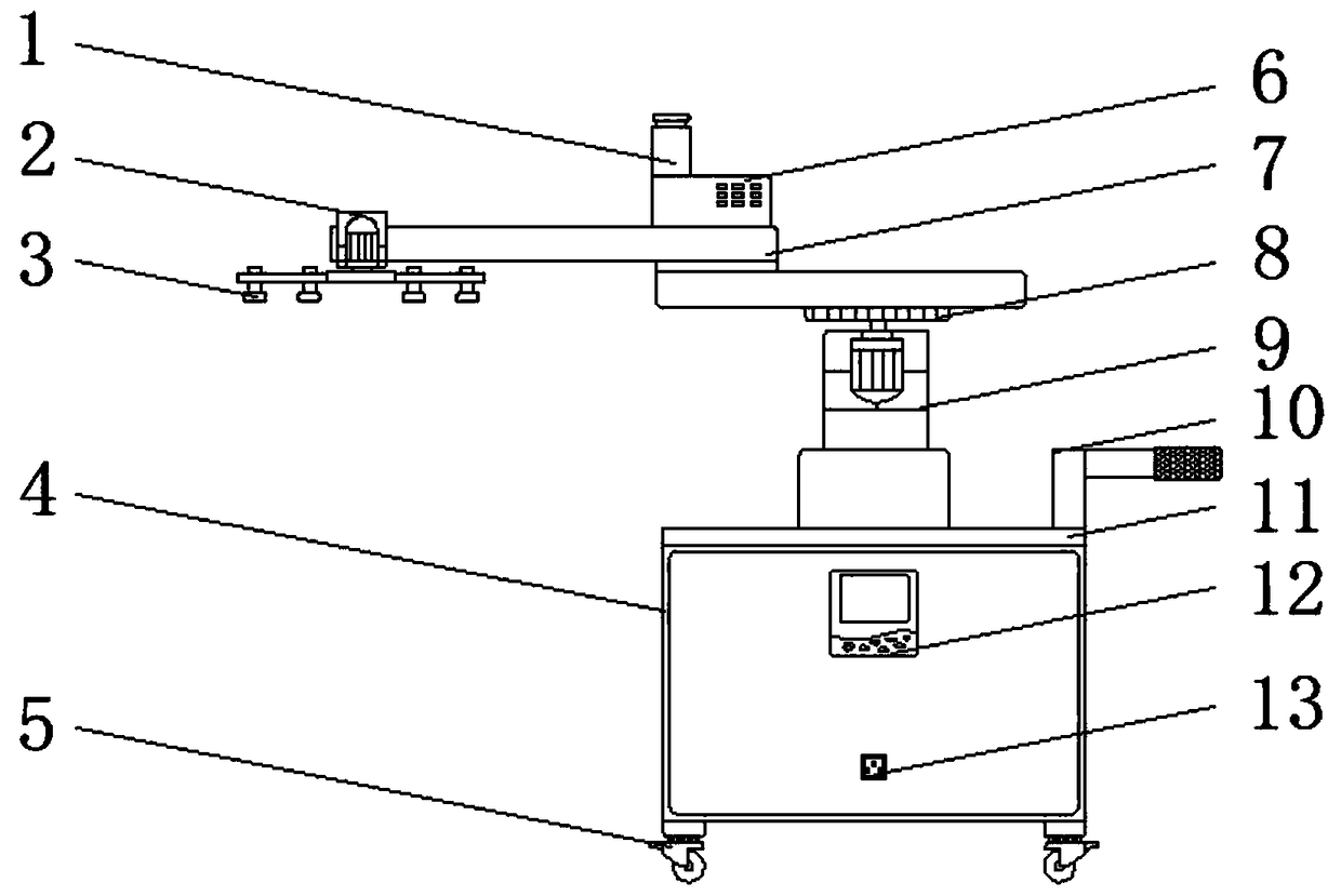
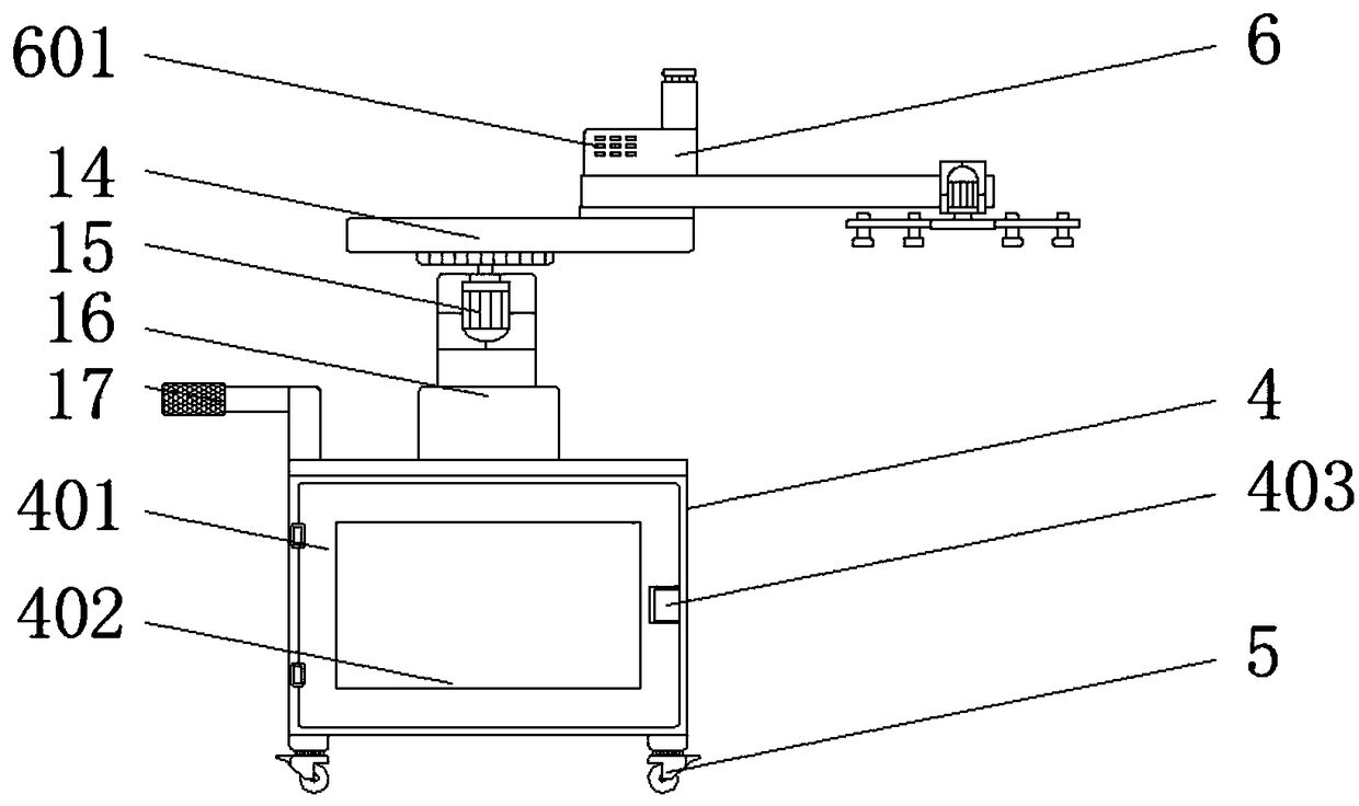
The invention discloses an automatic feeding device for the stamping manufacturing process. The automatic feeding device comprises an electromagnetic chuck, a machine case and a sliding platform cylinder. A supporting seat is fixedly installed at the top of the machine case, an electric cylinder is fixedly installed at the top of the supporting seat, and a protective shell is fixedly installed atthe top of the electric cylinder. A first motor is fixedly installed on the interior of a positioning plate, the electromagnetic chuck is fixedly installed at the output end of the first motor, a chipbox is fixedly installed at the top of the positioning plate, and an electronic module box is fixedly installed at the top of chip box. A handrail is fixedly installed at the top of the supporting seat, and the handrail is located on one side of the electric cylinder. A control panel is fixedly installed on the surface of the machine case, a supply hub is fixedly installed on the surface of the machine case, and the supply hub is located at the bottom of the control panel. The automatic feeding device for the stamping manufacturing process has the advantages of high working efficiency and simple operation in the using process of the automatic feeding device by arranging a series of structures.

Description

technical field [0001] The invention relates to the technical field of stamping devices, in particular to an automatic blanking device for stamping parts manufacturing process. Background technique [0002] With the continuous development of the times, the automatic blanking device for the stamping part process plays an important role in the blanking process. The automatic blanking device for the stamping part process is based on automation equipment and is specially designed to realize stamping automation according to the characteristics of stamping production. The equipment developed by unmanned production, most of the existing automatic blanking devices for stamping parts manufacturing process have only one gripper, which is inconvenient to carry out simultaneous clamping and replacement of products, and the work efficiency is low. Therefore, we propose a stamping parts manufacturing process Automatic unloading device to solve existing problems. Contents of the inventio...

Claims


Application Information

Patent Timeline
Patent Type & Authority Applications(China)
IPC IPC(8): B21D45/02
CPCB21D45/02
Inventor 谢银娒潘光平
Owner 宁波市拓欧金属制品有限公司
Why Eureka
Try Eureka