Ultra narrow gap MAG/MIG welding two-side wall fusing control device based on welding gun fan-shaped swing

A control device and narrow gap technology, applied in the direction of electrode support device, manufacturing tools, electrode characteristics, etc., can solve problems such as increased wire feeding resistance, unstable arc burning process, and difficulty in cleaning slag from ultra-narrow gap grooves, etc., to achieve Reliable fusion, the effect of high fusion reliability

Active Publication Date: 2018-11-06
武汉纳瑞格智能设备有限公司
View PDF8 Cites 2 Cited by
  • Summary
  • Abstract
  • Description
  • Claims
  • Application Information

AI Technical Summary

Problems solved by technology

The above-mentioned first to fourth side wall fusion control methods were developed by Japan. Among them, the two methods of twist welding wire and welding wire parallel rotation have been reported for a long time, but there are few actual production applications. The reason for the former is that the controllability of arc deflection is poor and the production of welding wire is complicated. The latter is difficult to reduce the filling area of ​​the welding groove to a more ideal state (the filling area is larger), and the hardware system of the welding torch is complex, and the welding wire has "jumping" caused by frequent beating changes of electrical contact points in the rotating conductive tip guide wire hole. "Arc sticking wire" and causing the arcing process to be unstable
The application history of wavy welding wire is long, but there are two "congenital" defects: first, it is difficult for the wavy welding wire after plastic deformation to be uniform in pitch, amplitude, and bending curvature; Uniform wear and smaller conductive contact area; the uneven curvature of the wave amplitude makes it difficult for the symmetrical center of the wave welding wire to coincide with the center plane of the current groove, and the angle and position of the arc deflection to the side wall are difficult to be consistent. The probability of non-fusion is high, which is the fundamental reason why this technical method tends to be eliminated in recent years
[0004] The deflection rotation at the end of the welding wire (that is, the rotation of the curved contact tip) can overcome the disadvantages of the wave welding wire, but the wire feeding resistance formed at the curved contact tip section increases, the fixed position in the guide wire hole wears seriously, and the filling area of ​​the welding groove is difficult. Limitations to a more ideal state are still evident
[0005] It is theoretically feasible to drive the arc to deflect to the two side walls by a magnetic field, but the structure of the welding torch is complicated, the reliability and controllability of the arc action position are poor, and there is no application in actual production
[0006] It is an invention technology of a university in my country to convey the insulating flux belt close to the two side walls. Its advantage is that the gap between the welding groove group can be as small as about 5mm, which can realize a more ideal ultra-narrow gap MAG / MIG welding; but the welding process It is too complicated, and the limitation of extremely difficult slag cleaning in the ultra-narrow gap groove is difficult to break through
[0007] The method of unilateral fixed side deviation (see invention patent ZL201610152254.4) has the advantages of excellent controllability of fusion of both side walls, high reliability of fusion, and long service life of the contact tip. The limitation that the mouth filling area is difficult to reduce to a more ideal ultra-narrow gap range

Method used


Image

  • Ultra narrow gap MAG/MIG welding two-side wall fusing control device based on welding gun fan-shaped swing
  • Ultra narrow gap MAG/MIG welding two-side wall fusing control device based on welding gun fan-shaped swing
  • Ultra narrow gap MAG/MIG welding two-side wall fusing control device based on welding gun fan-shaped swing

Examples


Embodiment

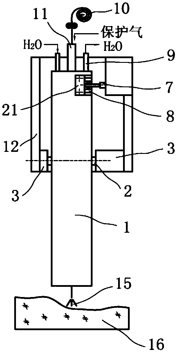
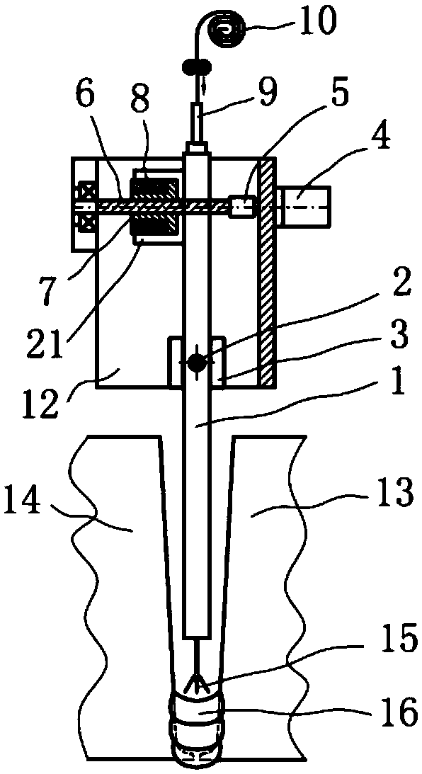
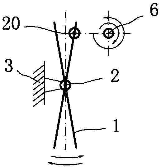
[0025] The present invention is mainly composed of ultra-narrow-gap MAG / MIG welding torch 1, fan swing fulcrum mechanism, fan swing driving mechanism, torch pulling device and welding torch outer seat 12 and is composed of five major components. The ultra-narrow gap MAG / MIG welding torch 1 is an integral plate structure, which integrates five functions of low-resistance guide wire, laminar air conduction, high current conduction, dual-circuit circulating water cooling and high-temperature insulation (see invention patents ZL201410487955.4 and ZL201510364758. 8). On both sides of the width of the middle part of the ultra-narrow gap MAG / MIG welding torch 1 in the height direction, there are two fan swing fulcrums, which are composed of a fulcrum seat 3, a hinge and a ball bearing; the fulcrum seat 3 is made of insulating material (such as polyoxymethylene) It is a cuboid structure, one end is fixed with the outer seat 12 of the welding torch, and the other end is equipped with a...


PUM


Abstract

The invention relates to an ultra narrow gap MAG / MIG welding two-side wall fusing control device based on welding gun fan-shaped swing. The ultra narrow gap MAG / MIG welding two-side wall fusing control device comprises ultra narrow gap MAG / MIG welding guns, a fan swing fulcrum mechanism, a fan swing driving mechanism, a pulling gun device and a welding gun outer base; the ultra narrow gap MAG / MIGwelding guns are connected through the fan swing fulcrum mechanism to be driven by the fan swing driving mechanism to do fan-shaped swing in the center in the width direction of a welding groove at the lower edge along a fan swing fulcrum. The ultra narrow gap MAG / MIG welding two-side wall fusing control device has the following advantages that a welding gun fan-shaped swing center can be accurately coincident with the center of a current welding groove, dissymmetry of action distances between electric arcs and the two side walls can be completely prevented, and the condition that a certain side wall is not fused due to not-identical distances between the electric arcs and the side walls can be reliably prevented; during fan-shaped electric arc swing, as electric arc centers with the highenergy density more easily acts on the positions nearby the side walls, the side wall fusing reliability is higher; and self-adaptation control over the swing amplitude and the actual groove width isachieved.

Description

technical field [0001] The invention belongs to the field of welding technology, and relates to a device for controlling the fusion of two side walls of ultra-narrow gap MAG / MIG welding based on the fan-shaped swing of a welding torch. Background technique [0002] The rapid popularization of industrial equipment in Suizhou to high capacity and high parameters, and the heavy-duty and large-scale industrial equipment lead to thicker and ultra-thick welded structures are becoming more and more widely used. The wide application of large-scale, heavy-duty and thick plates has led to a geometric increase in the amount of welding work, and the contradiction between manufacturing cycle, delivery time and manufacturing cost has become increasingly serious. This industrial background has promoted the rapid application of various welding methods in the field of equipment manufacturing. A narrow gap welding technology (Narrow gap welding). The biggest problem in narrow-gap and ultra-n...

Claims


Application Information

Patent Timeline
Patent Type & Authority Applications(China)
IPC IPC(8): B23K9/12B23K9/28
CPCB23K9/12B23K9/28
Inventor 张富巨
Owner 武汉纳瑞格智能设备有限公司
Why Eureka
Try Eureka