
Device for glass sleeve inside polishing

A glass sleeve and polishing cylinder technology, which is applied to grinding/polishing equipment, surface-polished machine tools, and parts of grinding machine tools, etc., can solve the problems of uneven spraying of polishing liquid, affecting visual sense, uneven scratches, etc. , to achieve the polishing effect and the effect of high efficiency, large polishing area and high practical performance

Inactive Publication Date: 2018-11-06
QUZHOU YANHANG BUSINESS CONSULTING CO LTD
View PDF0 Cites 1 Cited by
  • Summary
  • Abstract
  • Description
  • Claims
  • Application Information

AI Technical Summary

Problems solved by technology

[0002] With the development of science and technology and the progress of society, the country has been promoting the development of high technology. In the field of glass polishing technology, there has always been a relatively difficult technical problem. Glass is one of the most commonly used crystals, and the luminosity of its surface is extremely affected. Pay attention, if it is not suitable, it will affect its surface, resulting in uneven scratches and seriously affecting the visual sense. What's more, the internal polishing of the glass sleeve requires more advanced technical requirements. General equipment has polishing fluid spraying Problems such as unevenness, incomplete contact of the polishing surface and limited polishing area make the inside of the general glass sleeve very rough. This device effectively solves this problem

Method used


Image

  • Device for glass sleeve inside polishing
  • Device for glass sleeve inside polishing
  • Device for glass sleeve inside polishing

Examples


Embodiment Construction

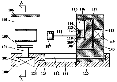
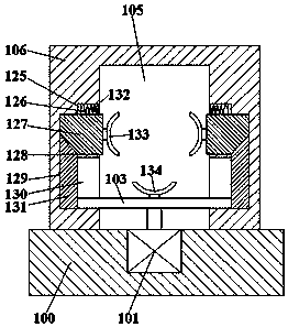
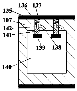
[0015] Such as figure 1 , figure 2 and image 3 As shown, the internal polishing of the glass sleeve of the present invention includes a base 100 and a firmware body 106 arranged on the top end surface of the base 100, and a polishing chamber 105 is provided through the left and right sides of the firmware body 106, and the polishing chamber 105 The front and rear inner walls are communicated with a first symmetrical guide chute 128, and the front and rear inner walls of the polishing chamber 105 are communicated with a symmetrical second guide chute 130, and the second guide chute 130 is far away from the polishing chamber. The inner wall of the end 105 communicates with a third guide chute 129, and the top of the third guide chute 129 communicates with the first guide chute 128, and the first guide chute 128 is slidably connected with a first guide chute. Slider 127, described first guide slider 127 is provided with side arc-shaped gripper 133 near described polishing cha...


PUM


Abstract

The invention discloses a device for glass sleeve inside polishing. The device for glass sleeve inside polishing comprises a base and a piece fixing machine body arranged on the end face of the top ofthe base. A polishing cavity is formed in the piece fixing machine body and penetrates through the left side and the right side of the piece fixing machine body. The front inner wall and the back inner wall of the polishing cavity are internally provided with symmetrical first guide sliding grooves in a communicating manner. The front inner wall and the back inner wall of the polishing cavity areinternally provided with symmetrical second guide sliding grooves in a communicating manner. The second guide sliding grooves are provided with third guide sliding grooves at the positions far away from the end inner walls of the polishing cavity in a communicating manner. The tops of the third guide sliding grooves communicate with the first guide sliding grooves. First guide sliding blocks areconnected into the first guide sliding grooves in a sliding and matched manner. The ends, close to the polishing cavity, of the first guide sliding blocks are provided with side arc clamping jaws. Thetops of the first guide sliding blocks are provided with elastic connection recovering device. The device for glass sleeve inside polishing is simple in structure, convenient to operate, large in polishing area, good in polishing effect and high in polishing efficiency and achieves close fit.

Description

technical field [0001] The invention relates to the technical field of glass polishing, in particular to the internal polishing of a glass sleeve. Background technique [0002] With the development of science and technology and the progress of society, the country has been promoting the development of high technology. In the field of glass polishing technology, there has always been a relatively difficult technical problem. Glass is one of the most commonly used crystals, and the luminosity of its surface is extremely affected. Pay attention, if it is not suitable, it will affect its surface, resulting in uneven scratches and seriously affecting the visual sense. What's more, the internal polishing of the glass sleeve requires more advanced technical requirements. General equipment has polishing fluid spraying Problems such as unevenness, incomplete contact of the polishing surface and limited polishing area make the inside of the general glass sleeve very rough. This device...

Claims


Application Information

Patent Timeline
Patent Type & Authority Applications(China)
IPC IPC(8): B24B29/08B24B41/06B24B41/02B24B47/12B24B57/02
CPCB24B29/08B24B41/02B24B41/067B24B47/12B24B57/02
Inventor 陈嘉旺
Owner QUZHOU YANHANG BUSINESS CONSULTING CO LTD
Learn More