Short fiber post-treatment equipment

A post-processing and short fiber technology, which is applied in the direction of bundling materials, bundling machine parts, forming non-bundling, etc., can solve the problem that short fibers have not been collected accurately, and achieve material saving, high working effect and strong continuity Effect

Inactive Publication Date: 2018-11-06
CHANGXING DEHONG MACHINERY CO LTD
View PDF1 Cites 2 Cited by
  • Summary
  • Abstract
  • Description
  • Claims
  • Application Information

AI Technical Summary

Problems solved by technology

[0005] The purpose of the present invention is to address the deficiencies of the prior art, to cut the sieved short fibers to equal lengths by setting a collecting mechanism, and to use a pressing mechanism to form a U-shaped iron wire, and then cooperate with a binding mechanism to cut the short fibers. The good short fibers are bundled and positioned, and then automa

Method used


Image

  • Short fiber post-treatment equipment
  • Short fiber post-treatment equipment
  • Short fiber post-treatment equipment

Examples


Embodiment 1

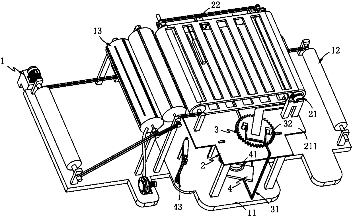
[0078] Such as figure 1 Shown, a kind of staple fiber post-processing equipment comprises:

[0079] A grouping mechanism 1, the grouping mechanism 1 includes a frame 11, a material conveying assembly a12 fixedly arranged on the frame 11, and a material conveying assembly arranged above the conveying assembly a12 and installed on the frame 11 component b13;

[0080] A material collection mechanism 2, the material collection mechanism 2 includes a cut-to-cut assembly 21 that is arranged on the frame 11 and cooperates with the conveying assembly b13 to slide up and down in the vertical direction, and a cut-to-cut assembly 21 that is slidably arranged on the cut-to-cut assembly 21 on the shearing seat 211 and with the pusher assembly 22 sliding along the width direction of the frame 11;

[0081] The material binding mechanism 3, the material binding mechanism 3 is arranged at the end of the shearing seat 211, which includes a delivery assembly 31 located below the shearing seat ...

Embodiment 2

[0146] Such as Figure 7 As shown, the components that are the same as or corresponding to those in the first embodiment are marked with the corresponding reference numerals in the first embodiment. For the sake of simplicity, only the differences from the first embodiment will be described below. The difference between this embodiment two and embodiment one is:

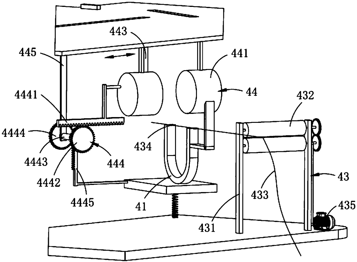
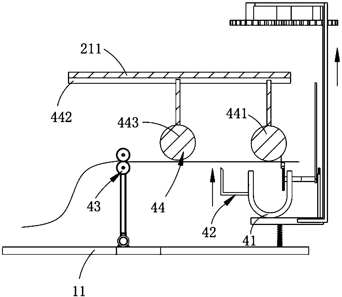
[0147] further, such as Figure 7 As shown, the delivery component 31 also includes:

[0148] Guide plate 311, two guide plates 311 are provided, which are fixedly arranged under the shear seat 211 and are arranged at an angle with any sideline of the shear seat 211;

[0149] It is worth noting that, on the one hand, by setting the guide plate 311, it acts as a guide to the iron wire 443, so that it can move to the guide groove 224 along a specific track, and then realizes the clamping work for short fibers; When the 443 is not working, the iron wire 443 is positioned and supported to keep the inclination angle se...


PUM


Abstract

The invention relates to short fiber post-treatment equipment which comprises a grouping mechanism, a collecting mechanism, a bundling mechanism and a compression molding mechanism, wherein the grouping mechanism comprises a rack, a conveying component a and a conveying component b; the collecting mechanism comprises a fixed cutting component and a push component; the push component is arranged ona cutting seat of the fixed cutting component in a sliding manner and slides along a width direction of the rack; the bundling mechanism is arranged at the tail end of the cutting seat and comprisesa lifting component and a torsion component; the lifting component is positioned below the cutting seat and is in running fit with the push component; the torsion component is fixedly connected with the lifting component and positioned above the cutting seat; the compression molding mechanism comprises a U-shaped seat, a cutting component, a delivery component and a molding component; the U-shapedseat is arranged on the lifting component; the cutting component is arranged on the U-shaped seat; the delivery component is positioned on one side of the lifting component; the molding component ispositioned above the lifting component and below the cutting seat; the molding component is arranged on the lower surface of the cutting seat in a sliding manner. According to the short fiber post-treatment equipment disclosed by the invention, the technical problem short fibers mixed in fiber bundles are accurately collected in the carding operation is solved.

Description

technical field [0001] The invention relates to the technical field of fiber finishing, in particular to short fiber post-processing equipment. Background technique [0002] In practice, a carding machine is used to remove the natural impurities contained in the cotton or wool fibers and to make the fibers of the sliver parallel, for which the previously prepared fiber bundle is clamped between the jaws of the nipper device so that the fibers A specific sub-length (called a "fiber tuft") protrudes at the front of the jaws. [0003] Patent No. CN101333701 discloses that in the equipment for fiber finishing or fiber selection of fiber bundles containing textile fibers, especially in the equipment for carding, the fiber bundles are supplied from the supply device to the fiber finishing device, especially Carding device in which there are clamping means for clamping the fiber bundle at a distance from its free end and a carding action is produced from the clamping point to the ...

Claims


Application Information

Patent Timeline
IPC IPC(8): D01G1/04B65B13/02B65B13/28
CPCD01G1/04B65B13/02B65B13/28
Inventor 乔海美
Owner CHANGXING DEHONG MACHINERY CO LTD
Why Eureka
Try Eureka