Flow bending type control valve and well system

A technology for controlling valves and flow patterns, which is applied in the direction of production fluid, wellbore/well components, and wellbore/well valve devices, etc., which can solve the problems of low sweep efficiency of injection fluid and premature entry of injection fluid into production wellbore, etc., to achieve Low cost, improved development efficiency, and high reliability

Inactive Publication Date: 2018-11-06
SICHUAN UNIVERSITY OF SCIENCE AND ENGINEERING
View PDF7 Cites 4 Cited by
  • Summary
  • Abstract
  • Description
  • Claims
  • Application Information

AI Technical Summary

Problems solved by technology

[0003] In liquid injection wells, it is generally desired to inject water, steam, gas, etc. into the formation uniformly, but due to the pressure drop along the wellbore and the heterogeneity of the formation, the fluid flows non-uniformly in the formation, making the sweep efficiency of the injected fluid low, eventually leading to premature entry of injection fluid into the production wellbore

Method used


Image

  • Flow bending type control valve and well system
  • Flow bending type control valve and well system
  • Flow bending type control valve and well system

Examples


Embodiment 1

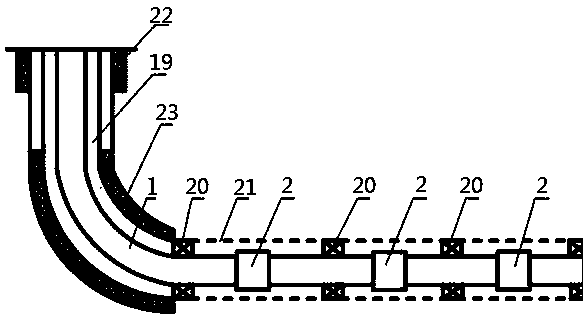
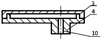
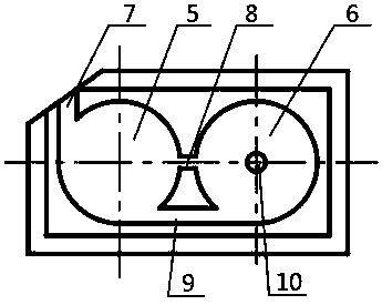
[0027] Example 1, such as Figure 1-Figure 6 As shown in , the present invention is a baffle type control valve and its well system, which is characterized in that: it includes a completion string 1 and a baffle type control valve 2; the heel end of the horizontal section of the completion string 1 is There are multiple groups of baffle control valves 2 that are closed at intervals in the direction of the toe end; the baffle control valve 2 includes a cover plate 3 and a valve body 4, and the cover plate 3 and the valve body 4 are interference fit; the valve body 4 is provided with a circular chamber 5 and a control chamber 6, and the circular chamber 5 is provided with a liquid inlet 7 connected to the outside, and the circular chamber 5 and the control chamber 6 respectively pass through the flow channel A8 and the flow channel B9 is connected; the bottom of the control chamber 6 is provided with a nozzle 10 communicating with the lower end of the control chamber 6 and the v...

Embodiment 2

[0031] Embodiment 2, carry out further optimization design on the basis of embodiment 1, as Figure 7 and Figure 8As shown in , a baffle chamber 11 is provided between the circular chamber 5 and the control chamber 6; the baffle chamber 11 communicates with the circular chamber 5 through the flow channel C12 and the flow channel D13; The chamber 11 communicates with the control chamber 6 through the flow channel E14. The baffle chamber 11 is provided with more than one, and a plurality of baffle chambers 11 are connected in series or in parallel, and the shapes of the baffle chamber 11 and the control chamber 6 are respectively one of geometric figures; The shape of 11 can be any shape such as a circle, a square, etc. The number of baffle chambers 11 can be one or more, and multiple baffle chambers 11 can be connected in parallel or in series in the valve body 4 . When the fluid flows in the baffle chamber 11, the flow velocity and direction are changed, which increases the...


PUM


Abstract

The invention discloses a flow bending type control valve and a well system. The flow bending type control valve and the well system comprise a well completion tubular column and the flow bending typecontrol valves. Multiple groups of the flow bending type control valve are sequentially arranged at intervals on the horizontal section of the well completion tubular column in the direction from theheel end to the toe end in a sealing mode. The flow bending type control valves comprise covering plates and valve bodies; the covering plates and the valve bodies are in interference fit; the valvebodies are provided with circle cavities and control cavities; the circle cavities are provided with liquid inlets communicating with the outside; the circle cavities and the control cavities are connected correspondingly by flow channels A and flow channels B; and spraying nozzles communicating the control cavities with the lower end of the valve bodies are arranged at the bottoms of the controlcavities. According to the flow bending type control valve, pressure drop flowing the flow bending type control valve is determined based on liquid physical properties (viscosity, density, flow velocity, moisture content, vapor liquid ratio and the like); pouring/extraction sections of oil deposit can be adjusted automatically; self-adjusting and self-control of the oil deposit are achieved; and due to the fact that moving parts and control cables are omitted, reliability is high and the cost is low.

Description

technical field [0001] The invention relates to the technical field of tools for underground fluid flow control in oil drilling, in particular to a baffle type control valve and a well system thereof. Background technique [0002] In the production well, due to the heel-toe effect of the wellbore and the heterogeneity of the formation, the flow distribution along the wellbore is uneven, that is, the production of the bottom hole and the high-permeability well section is obviously higher than that of the low-permeability well section. The degree of recovery of the permeability well section. In edge / bottom water reservoirs, the flow distribution along the wellbore is not balanced, and the edge / bottom water will enter the wellbore prematurely. After the water enters the wellbore, due to its far mobility Stronger than crude oil, the output of oil is greatly reduced. Therefore, adjusting the fluid production profile of the formation can prevent water or gas cones, minimize water...

Claims


Application Information

Patent Timeline
Patent Type & Authority Applications(China)
IPC IPC(8): E21B43/12E21B34/06
CPCE21B34/06E21B43/12
Inventor 阳明君周敏刘少北李涛干斌史君林
Owner SICHUAN UNIVERSITY OF SCIENCE AND ENGINEERING
Why Eureka
Try Eureka